Description.
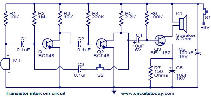
Here is a simple but effective intercom circuit that is based fully on transistors.The circuit is based on a three stage RC coupled amplifier. When the pushbutton S2 is pressed, the amplifier circuit wired around T1 & T2 becomes an astable multivibrator and starts producing the ringing signals. These ringing signals will be amplified by the transistor T3 to drive the speaker. When the push button S2 is released the circuit will behave as an ordinary amplifier and you can talk to the other side through it.
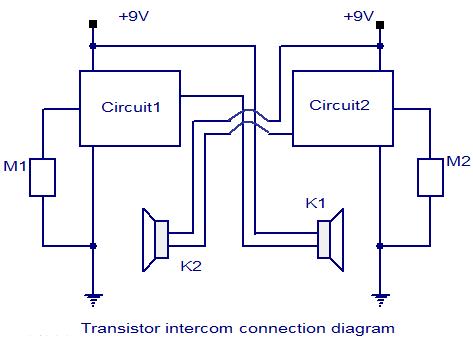
To construct a two way intercom, make two identical copies of the circuit given below and connect it according to the given connection diagram. The stand by current consumption of this circuit is around 20mA.
Circuit diagram with Parts list.
Connection diagram.
Notes.
- Assemble the circuit on a good quality PCB.
- Use 9V PP3 battery for powering the circuit.
- The Mic M1 can be condenser micro phone.
- Use push to ON type push button switch for S2.
- Use a slide switch for switch S1.S1 can be used to power the circuit.
109 Comments
sir, u said will be using 2 identical ckts. accordint to 2nd connection diagram where will we connect output of 2 speakers if i implement single ckt and 2 speakers (one as master and other as slave).
is it POSSIBLE?
I making this project as my mini project but instead of wired i am makin wireless can you help me to make it wireless pls admin sir……
Can u pls send me abstract and layout of transistor intercom ckt project …
AOA
the project sounds easy and interesting… i want to do this for my semester project for that i need complete theory information of each and every component as this will help me in understanding the project… email
id :ra42325@gmail.com
please mail me as early as possible
looking forward for your positive response thanks
Hi sir, I am a electronic hobbyist .your circuit is good but it not give soft sound there is very noise. Sir please tell me how to filter sound.
I have made this circuit with bd135 but there is too much noise and I can’t get a clear voice….can you plz tell me why is this happening, I making it for my college project so need help asap.
will any one plz tell me what would be the overall component cost ?
plz
Without box it may cost you around INR 150/-
hi i have a few questions for this circuit
1st-can i use bc547 instead of bc548…
2nd-if this is a wireless two way communication(which seems like it) i would like to know how to tune them to their frequencies and what is the range
3rd-how what is the effective range of this circuit..
hope u can reply u can reply in my email
How do you increase the volume of the output from the speaker?
Hi,
Im building this circuit for a project at college. Would appreciate a full circuit analysis if anyone could supply one. This would really help me out, thanks in advance.
September 28, 2010 at 9:03 am
Hi Saad it is a 3 stage common emitter amplifier. first 2 stages for voltage amplfication for the mic and 3rd transistor is the power amplifier for the speaker in the talk mode module. the first 2 transistor becomes a nultivibrator when call button is pushed ad the sound is amplified by the 3rd transistor and fed to speaker. ensure that mic and speaker are not kept closer to avoid acoustic feedback.
can any 1 tell me that what is the practical approach of transistor intercom ckt ? please
Hi,
would it be okay if I left out both switches?
And how many watts should the speaker be?
I also replaced Q3 with a bc548 and the sound was very soft and there was a lot of ringing in the output.
hi omar
did ur circuit worked with replacing bel 187 with bc 548 and how?
plz reply
hi there this is a very interesting circuit, i chose to build this to use between my kids room and the living room. i built 2 twin circuits exactly to plan substituting BEL187 with S8050. both push button alerts ring however no voice is heard when in talk mode. there is a faint feedback sound so i know both speakers are, tapping the mic also produces a noise but no voice ?? i used 2x 0.5watt 8 ohm speakers. any help would be much apreciated thanx
Seetharaman, can i replace bel187 with TIP41 power transistor?
i want to improvise the system to a multi to multi level 2 way intercom so can you please suggest me some ideas……
also i have the idea of using a dialer for the multi level, i doubt that whether it is possible please help me with my idea
thank you so much for your wounderful project looking forward for your respose
sir can you help what is the replacement for bel187 because out of stock
Hi Patrick you can use 2N1711, S8050 BD135 2N2218 etc NPN medium power transistors.
The earphone does work with the circuit, but when I build two identical circuit in one board with one 9v supply, the circuit creates a clicking and unwanted noise. It only allow using either circuit1 or circuit2 to have a clear voice output. I was trying to make a motorcycle intercom out of your circuit, can you give me some pointers on what I might miss. Thanks again.
Hi let circuit 1 be energised by its own battery and similarly circuit 2 should be energised by its own battery. If single battery is used you may have to have proper decoupling for the circuit 1 & 2 if single 9 volt supply is used.
Mic M1 is electret condenser mic used in tape recorders.
You can use standard 32 ohms stereo earphones in parallel in place of speaker shown.
Thanks man! The circuit really works. I have some few question regarding the speaker, i would like to replace it with earphones, can you give me instructions on how will this be possible. Thanks in advance.
I like this circuit , but pls give me more and clear information about mic… I am waiting for u’r repply..
hey,
the project sounds easy and interseting… me gona try dis for my semester project for tht need complete theory information of each and every component as this wil help me in understanding the project… email id :xainy_qureshi@hotmail.com
luking forward for your positive response thanx
Circuittoday,
This is an awesome circuit, but i want to ask if you can take me through the process of design the circuits myself. To some extent i can design circuitto meet certain needs, but a major challenge is how to choose the values of components. I will appreciate it if you can teach me how you choose the values of this circuit for instance. From the two stage voltage amplification to the power amplifier.. Thanks guys
hello sir. can u pls email me the procedures and analyis.
CAN WE GET MORE IMFORMATION
THERE IS NO FULL IMFORMATION
can u send full explanation about this project
can you please specify the range upto which this system is functional? as in, whats the maximum distance that the 2 mics can be separated by?
can somebody mail the complete circuit analysis of this project I just need it for my school project.. thanks in advance. .
hi! can anyone pls tell me the maximum range the circuit can work efficiently?
can I use any kind of speaker for this circuit???
use a general purpose speaker with 8 ohms impedance. Ask for a 8 ohm speaker in a radio shop.
is this circuit actually works by following the connections above
Specify which part you did not understand?
what i meant was if this circuit would work.?, especially when i follow the connections.?
Well, it will work. BTW, be careful about the transistor pins while soldering them.
Can you mail me the complete circuit flow explanation on this diagram. its just that i need it for my presentation. @ francisdacs07@yahoo.com
Can you mail me the complete circuit flow explanation on this diagram. its just that i need it for my presentation. @ francisdacz07@yahoo.com this is the real email add, i made a mistake
hey! anish….. can you plz help me for this project…….i am having some problems regarding this
Hello sir where is he second circuit?
can you please explain the complete working of the project
Helo,plz can you guz mail to me explaining or complete analysis of how the circuit works.information given here is not much to digest or convince the panel of judges.the need is quite urgent plz.
Pls sir wats the working of the transistor intercom?. I need a detailed explanation for my school project. Pls sent to my mail. Regard!
Hi Roy this is an independant pair cannot not be hooked to any other system. This is a simple audio amplifier with astable oscillator to call.
THIS IS REALY A TRENSPLITER CAM RECIVER UNIT
CAN I CONNECT WITH OTHER UNIT OF INTERCOM FOR TALKING ???????????? AND WHER IS THE ANTENA IS GIVEN ????????
can u mail me the detailed explanation of the above circuit as soon as possible….plz
I am unable to figure out the proper layout for LED lights using 2 double A batteries, with a rocker switch.
plz sir send me layout of “Transistor intercom circuit.”
my mail id is yogesh7828@gmail.com
and pls suggest any other replacement of BC187..
plz send procedure of this circuit to my email anjireddyece@gmail.com
Can u plz tell me about the maximum range of distance for this intercom?
.hi its me again ,,I have use telephone flat wire for our intercom it is approximately 20m. And my problem is that the sound produce decrease . . .we can here the buzzer but it is not enough to get the attention of the receiver . ..is there any solution to maximize the sound of the buzzer? a loud enough to get the attention of the receiver?, we have 9volts power supply . . i use the bd137 because its the only transistor i found in the market..please help as soon as posible
hello guyzzz,, what kind of mic will i use???
hi!! can i use any 8 ohm speaker?? what do you think is the most suitable wattage of the speaker i should use?? thank you!! ^^
You can also use B1446 R instead of BEL 187. I made this intercom and it works A1 with this transistor but i do not understand how this works plz anybody who can tell me how this amplifies i have to give presentation for this circuit on 1st january ……… plz thnxx
usama_1s@hotmail.com
I really appreciated your wonderful response….Seetharaman . . . .thank you very much
wow! it is a must to really compliment this circuit,;’. it’s vastly great;,’ i made the circuit and im very happy right now’;,;’ thanks circuitstoday’.’ ur d best’,;’ more power to you guys;’,;’
Hi Christiane you can use 2N1711, 2N2218, 2N2219, SL100, 8050, BD135, BD137, BD139 etc any medium power NPN transistor.
Hoping for your response immediately.. .thank your kindness
can I use other type of Q3? I cant find it in the market . .. they always say its out of stock … . .please any transistor that i can replace BEL187 . . .i,m rushing my project and this circuit is my only hope. . .thanks
helo sir,.; could you also publish a circuit in relevance with this one a two-way intercom using at least a 5watt ic amplifier. there will be no mics rather, an 8ohm 0.25 watt speaker could act as the pick-up and output at the same time using a dpdt switch,’,’ i think, theoretically, this would be simple an easy to assemble/.,’; thanks very much;l,;
hello sir!!! can u mail me the detailed explanation of the above circuit at anshugoyle@yahoo.com
thank you very much seetharaman! 🙂
Hi Aki ensure that you are using electret condenser mic and its polarity is taken care while connecting. moving coil mic of low impedance will not work you have to use matching transformer and delete R1 which is giving polarizing voltage to electret mic.
what will i do?
i tried it with q3 as 2n2219 but the speaker only amplifies the sound of q1 and q2 going off and on. i do have a mic but it cant be detected. 🙁
can someone tell how i can make 4 way intercom circuit
Hi Gokula You can carryout what ever modifications you want if it works nicely, please give us the feedback.
what will happen when i connect higher range of resistor and i want to know feedback for my comments
could i use SPDT switch
can i use some other range of transistor
can i use alarm signal instead of speaker
the can any transistor can replace the BEL187??
how iz the range of the intercom iz controoled,,,,n eats its range,,,,,,,?
a.a wat iz multivibrater,?
Hi Fahad one is local unit and the other is remote unit hence they have to have there own batery for calling purposes. 0.1uF is available in ceramic disc and they are dirt cheap comparing to electrlytic ones. the multi vibrator function to call the people available on the other end just like telephone ringing to get attention in the remote unit.
this circuit worked.,,,
i want to ask
1)why to use two voltage and power amplifier.
2)the circuit worked when i replaced non ploar cap wit polar ones?
3)what is nulvibrator?why is happening
waiting ….
i have to give viva
thanks
Hi Saad it will work, but to make a call you require some tone to get the attention from the other side, hence a push to call is provided.
thanks.the circuit performed well,but it worked without the connection of push to on switch
Hi Fahad S1 is a bell push type of switch (push to switch on release to off – non latching type)push to produce tone – to call. release to talk and listen. through connecting wire wire-up this box speaker to other intercom unit and vice versa.
hi i am using bred boar ,should i connect the speaker wire
directly in the board or through circuit connecting wire?
once i have pused the s2,then what should be done to reset
the circuit,?
regards
Hi Fahad C1, C2 & C3 are ceramic discs, hence non polar (polyster or polycabonate type can be used but they are bulky in size).
c1,c2 are non polar?
can u give me the layout???plz
hi,the above mic in the circuit is elec condenser mic?
i want to make the PCB design.is there any software.
Hi Jatin 3 tag condencer mics are available. one is common next is power supply 1.5 to 9 volt and the third one is signal (audio)output. Use this type of mic in an old mic casing with 1.5 volt button cell and use a coaxial cable to connect to amplifier mag mic input. ( these conencer mics are having built in amplifier to take care). if you use a two pin condencer mic you can use phanthom supply from the amplifier itself to energize the mic. and take audio signal through the same coaxial cable like TV antenna booster circuits.
How to make a condencer mic for pa amplifire
How to make a mic for pa amplifire
Hi Saad it is a 3 stage common emitter amplifier. first 2 stages for voltage amplfication for the mic and 3rd transistor is the power amplifier for the speaker in the talk mode module. the first 2 transistor becomes a nultivibrator when call button is pushed ad the sound is amplified by the 3rd transistor and fed to speaker. ensure that mic and speaker are not kept closer to avoid acoustic feedback.
sir can u plz send me the analysis part of the circuit.thanks. at
s.qaisar@yahoo.com
Hi neelavathi use 2N1711 or BD135 or 2N2218 or 2N2219 for Q3 it required higher capacity transistor than BC548.
can we replace Q3 by Q2.
pls can u send me how i can connect the two circuit along eachother an how i can add amplification ecause i intend to use both a.c and d.c power supply on my cicuit, thank u
Hi Saad it is just a bell push switch (like home bell switch). You can use it as door phone. up to 100 feet or so you should not face any problem. cable should be atleast of 1sq mm cross sectional area
hello sir,is the switch S2 is like the home bell? and will i be able to use it as a home intercom(any range problem)?
i am waiting for your reply as early as you can.thanks
i’m confused about connecting s2 on the board i cant’ figure out how it should be i need an answer as soon as possible its my graduation project so please help…..
there is no connection show b/w these circuits
how i connect these two circuits
Dear Deepika Q1 & Q2 are amplifiers to increase the signal level from the condenser microphone M1. Q3 is the power amplifier to drive the speaker. For calling the remote person Q1 & Q2 act as a flip flop oscillator by pushing the S2 switch, its signal is amplified by Q3 and fed to the remote speaker for attention. Please see the inter connecting diagram for the position of speakers. Enjoy reading Circuits today try to assemble them you will love them.
seetharam, Can you mail me the complete circuit flow explanation on this diagram. its just that i need it for my project report. pls send me full explaination or full project report on low cost intercom
thnks …..
I can not find Q3( BEL 187 ) in the data shit , could you please introduce it’s equivalant.
thank you
can someone give a detailed explanation about the working of this circuit
i would like to get the introductory aspect of this transister intercom
circuit
serach
can use of 12V source be used instead of the design 9V?