Description.
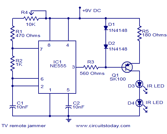
Here is the circuit diagram of simple but highly effective TV remote jammer circuit. Most of the TV remotes have 38KHz operating frequency. A flood of IR beams in the same frequency can easily confuse the TV receiver and this is the operating principle of our jammer. The circuit is nothing but an astable multivibrator based on NE555 IC. The output of NE555 is amplified using a PNP transistor SK100 to drive the IR LEDs. Not only TV remotes, but any IR remotes operating in the 38KHz frequency region can be also jammed by using this circuit.
Circuit diagram.
Notes.
- The circuit can be assembled on a Vero board.
- Use a 9V PP3 battery for powering the circuit.
- Mount the IC on a holder.
- POT R4 can be adjusted to exactly match the jammer’s frequency to the remotes frequency. This adjustment is very essential for effective jamming.


42 Comments
hey i got the LEDs lightened up( saw them from digitical camera) yet the jammer wont work at all 🙁 i tried changing potentiometer still remote still works
are all components available in store (electronic) ?
yes
How to adjust R4 to get matching frequency
instead of sk100 which transistor can i use
BD140, S8550, CK100, 2N2905
i want to make every electonic matterial on remot suppose we want to switch on the fans by pressing switch of he remote can switch on h fans
You can buy the remote receiver and use it with a relay to switch fan on / off by using the on / off channel of the remote for it.
is this circuit will jame the universal tv remote
Yes it can jam any IR remote control
Does C1 and C2 are electrolytes or ceramics?
Hi builder C1 & C2 are ceramic disc capacitors.
Hi Vamsi it is working only the frequency adjustment requires little patience and trials.
is it working for any one
Seetharaman, have you use this circuit to jam any TV Receiver Sets before? Please reply me because i want to build this circuit
Hi Rex When this device is transmitting IR signal, the TV will not respond to commands from the original TV remote control, provided the frequencies of both are matched as explained in the text.
Seetharaman, Has any person tried this circuit before? Can this circuit jam TV receiver sets?
I need it urgent please…..
I need a mobile gammer circuit for a certain area range to block the incomeing call.
Could you please provide me?
check your spelling..mobile signal jamming by public user is illegal in most countries
really it does not work………….
i got 45khz at output will my circuit jam it or not?
Please see the note. try adjusting the pot (to adjust the frequency)till it jams the operating remote.
What are the alternatives to the SK-100 transistor?
BD136 2N2905 8550
Hi….my circuit connection is working and i can see the ir led light wit camera but i keep infront of tv means the tv remote is still working ..pls give me idea
What hapens to the circuit when i use 220ohm instead of 180ohm as R5
hi
you can see inferared led,s light whit mobile camera when you push a button on tv remote … i build these circuit but it dosen’t work becuse i can’t see light whit camera and tv remote still working.
Any body know means pls tell me
hi2012 at 1:26 pm
HI-I NEED A CIRCUIT TO TEST SATTELITE RECEIVER EQUPMENT AFTER REPAIR THAT WITHOUT ADJEST DISH BECAUSE I WANT TO FINSH AND TEST IN MY SHOP
aadi
HI-I NEED A CIRCUIT TO TEST SATTELITE RECEIVER EQUPMENT AFTER REPAIR THAT WITHOUT ADJEST DISH BECAUSE I WANT TO FINSH AND TEST IN MY SHOP
kindly tell me how this circuit (remote jammer) having 555 i.c works.
mean;
1 ; how it generate the REQUIRED pulses
2 ; how that pulses cancle out the effect of the t.v IR
THANKS
Hi Shinj use any of the following BEL100P, BEL188, 8550, 2N2905, BD136, BC327
Please give a substitute transistor in the place of SK100
can the ir sensor TSOP 1836 recive this remote jammer ir led signal?????plz reply sir.plzzzzz.
😀
pleas give me universal remote control working remote recever circuit diagram
how can we connect a preset ( variable resistor)
thank’s it working !!!!
Hi Bryce within the room only being IR
what is the wireless range of this circuit
are the leds the antenna
nasıl çalışır ben devreyi yaptım amma çalıştıramadım