Description.
Here is a versatile night light circuit that can be used in two modes. The dimmer mode and a flashing mode. The circuit is based on dual opamp LM 358 and associated components.
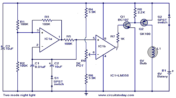
The first opamp IC1a is wired as a pulse generator and the second opamp is wired as a comparator. When the switch S1 is open the circuit is in dimmer mode where the intensity of the lamp can be varied by varying the POT R9. When the switch S1 is closed the circuit works in the flashing mode where the rate of flashing can be varied by varying adjusting the POT R9. The transistors Q1 and Q2 forms a complementary pair to drive the lamp.
Circuit diagram with Parts list .
Notes.
- Comparators IC1a and IC1b belongs to same IC LM 358.So the power supply is (pin 8 & 4) shown connected to only one comparators. No problem.
- Use a 6V lead acid or SMF battery for powering the circuit.
- Switch S2 can be used as a ON OFF switch.
- All electrolytic capacitors must be rated at least 10V.
7 Comments
What would you advise for an alternative for SK100 and BC107?
Good day, sir! i picked this circuit for my final project in my subject. I’ve bought all the components except the SK100 and BC107. Can you suggest an alternative for these two transistor for this circuit to work? Thank you.
i liked dis project,but i didn’t get demo n full description for dis pls tell me whch site i will search,pls help me .
why the S1 is not working????
can give me answer quickly????
A limiting resistor in collector of Q1(BC107) is mandatory. Otherwise Q1 will disipate too much power and eventually break down. For this resistor, a value of 150Ω…470Ω will do the job.
I don’t understand im very very thick XD
How does a servo motor HS-422, controls a robot to follow a black line using pure analogue design? If possible send me a circuit diagram of full system.