Ultrasonic range finder using 8051 .
A simple ultrasonic range finder using 8051 microcontroller is presented in this article. This ultrasonic rangefinder can measure distances up to 2.5 meters at an accuracy of 1 centi meter. AT89s51 microcontroller and the ultrasonic transducer module HC-SR04 forms the basis of this circuit. The ultrasonic module sends a signal to the object, then picks up its echo and outputs a wave form whose time period is proportional to the distance. The microcontroller accepts this signal, performs necessary processing and displays the corresponding distance on the 3 digit seven segment display. This circuit finds a lot of application in projects like automotive parking sensors, obstacle warning systems, terrain monitoring robots, industrial distance measurements etc.
HC-SR04 ultrasonic module.
HC-SR04 is an ultrasonic ranging module designed for embedded system projects like this. It has a resolution of 0.3cm and the ranging distance is from 2cm to 500cm. It operates from a 5V DC supply and the standby current is less than 2mA. The module transmits an ultrasonic signal, picks up its echo, measures the time elapsed between the two events and outputs a waveform whose high time is modulated by the measured time which is proportional to the distance. .The photograph of an HC-SR04 module is shown below.

The supporting circuits fabricated on the module makes it almost stand alone and what the programmer need to do is to send a trigger signal to it for initiating transmission and receive the echo signal from it for distance calculation. The HR-SR04 has four pins namely Vcc, Trigger, Echo, GND and they are explained in detail below.
1) VCC : 5V DC supply voltage is connected to this pin.
2) Trigger: The trigger signal for starting the transmission is given to this pin. The trigger signal must be a pulse with 10uS high time. When the module receives a valid trigger signal it issues 8 pulses of 40KHz ultrasonic sound from the transmitter. The echo of this sound is picked by the receiver.
3)Echo: At this pin, the module outputs a waveform with high time proportional to the distance.
4) GND: Ground is connected to this pin.
HC-SR04 timing diagram.
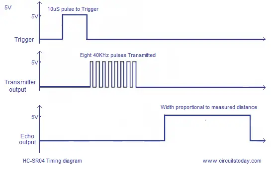
From the timing diagram, you can see that the 40KHz pulse train is transmitted just after the 10uS triggering pulse and the echo output is obtained after some more time. The next triggering pulse can be given only after the echo is faded away and this time period is called cycle period. The cycle period for HC-SR04 must not be below 50mS. According to datasheet, the distance can be calculated from the echo pulse width using the following equations.
Distance in cm = echo pulse width in uS/58
Distance in inch = echo pulse width in uS/148
Ultrasonic range finder using 8051- Circuit diagram.
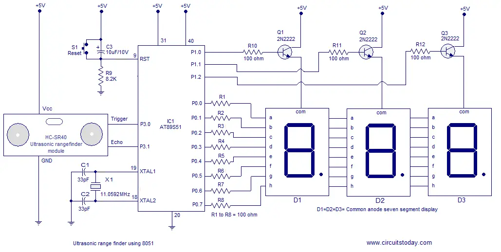
The ultrasonic module is interfaced to the microcontroller through P3.0 and P3.1 pins. Port0 used for transmitting the 8 bit display data to the display and port pins P1.0, P1.1, P1.2 are used for transmitting display drive signals for the corresponding display units D1, D2, D3. Push button switch S1, capacitor C3 and resistor R9 forms a de-bouncing reset circuitry. Capacitors C1,C2 and crystal X1 are associated with the clock circuit.
Program.
ORG 00H                // origin
MOV DPTR,#LUT          // moves the address of LUT to DPTR
MOV P1,#00000000B      // sets P1 as output port
MOV P0,#00000000B      // sets P0 as output port
CLR P3.0               // sets P3.0 as output for sending trigger
SETB P3.1              // sets P3.1 as input for receiving echo
MOV TMOD,#00100000B    // sets timer1 as mode 2 auto reload timer
MAIN: MOV TL1,#207D    // loads the initial value to start counting from
      MOV TH1,#207D    // loads the reload value
      MOV A,#00000000B // clears accumulator
      SETB P3.0        // starts the trigger pulse
      ACALL DELAY1     // gives 10uS width for the trigger pulse
      CLR P3.0         // ends the trigger pulse
HERE: JNB P3.1,HERE    // loops here until echo is received
BACK: SETB TR1         // starts the timer1
HERE1: JNB TF1,HERE1   // loops here until timer overflows (ie;48 count)
      CLR TR1          // stops the timer
      CLR TF1          // clears timer flag 1
      INC A            // increments A for every timer1 overflow
      JB P3.1,BACK     // jumps to BACK if echo is still available
      MOV R4,A         // saves the value of A to R4
      ACALL DLOOP      // calls the display loop
      SJMP MAIN        // jumps to MAIN loop

DELAY1: MOV R6,#2D     // 10uS delay
LABEL1: DJNZ R6,LABEL1
        RET

DLOOP: MOV R5,#100D    // loads R5 with 100D
BACK1: MOV A,R4        // loads the value in R4 to A
       MOV B,#100D     // loads B with 100D
       DIV AB          // isolates the first digit
       SETB P1.0       // activates LED display unit D1
       ACALL DISPLAY   // calls DISPLAY subroutine
       MOV P0,A        // moves digit drive pattern for 1st digit to P0
       ACALL DELAY     // 1mS delay
       ACALL DELAY
       MOV A,B         // moves the remainder of 1st division to A
       MOV B,#10D      // loads B with 10D
       DIV AB          // isolates the second digit
       CLR P1.0        // deactivates LED display unit D1
       SETB P1.1       // activates LED display unit D2
       ACALL DISPLAY
       MOV P0,A        // moves digit drive pattern for 2nd digit to P0
       ACALL DELAY
       ACALL DELAY
       MOV A,B         // moves the remainder of 2nd division to A
       CLR P1.1        // deactivates LED display unit D2
       SETB P1.2       // activates LED display unit D3
       ACALL DISPLAY
       MOV P0,A        // moves the digit drive pattern for 3rd digit to P0
       ACALL DELAY
       ACALL DELAY
       CLR P1.2       // deactivates LED display unit D3
       DJNZ R5,BACK1  // repeats the display loop 100 times
       RET

DELAY: MOV R7,#250D        // 1mS delay
LABEL2: DJNZ R7,LABEL2
        RET

DISPLAY: MOVC A,@A+DPTR   // gets the digit drive pattern for the content in A
         CPL A            // complements the digit drive pattern (see Note 1)
         RET
LUT: DB 3FH               // look up table (LUT) starts here
     DB 06H
     DB 5BH
     DB 4FH
     DB 66H
     DB 6DH
     DB 7DH
     DB 07H
     DB 7FH
     DB 6FH
END
About the program.
The first part of the program sets the initial conditions. Port 0 and P0rt 1 are set as output ports for sending digit drive patterns and digit drive signals respectively. Port pin 3.0 is set as an output pin for sending the trigger signal to the ultrasonic module for starting transmission and port pin 3.1 is set as an input pin for receiving the echo. TMOD register of the microcontroller is so loaded that the Timer 1 operates in mode2 8 bit auto-reload mode. Timer 0 of the microcontroller is not used here. In the next part of the program (loop MAIN) the TL1 and TH1 registers of Timer1 are loaded with the initial values. TL1 is loaded with the initial value to start counting from and TH1 is loaded with the reload value. This is how timer 1 in mode 2 works: When TR1 bit of the TCON register is set the TL1 starts counting from the initial value loaded into it and keeps counting untill roll over (ie; 255D). When roll over occurs, TF1 flag is set and TL1 is automatically loaded with the reload value stored in TH1 and the sequence is repeated until TR1 is made low by the program. The TF1 goes high at the first roll over and if you want it as an indicator for each roll over, you have to clear it using the program after each roll over. In the next part of the MAIN loop P3.0 is set high for 10uS and then cleared to make 10uS triggering pulse. The ultrasonic module issues a 40Khz pulse wave form after receiving this trigger and the program waits until a valid echo is received at P3.1. The pulse width of the echo signal is proportional to the distance to the obstacle and so the next job of the program is to measure the pulse width. Whenever there is a valid echo pulse at P3.1, the Timer1 starts and it counts from the initial value to 255 ie: 255-207= 48 counts. Then the counter restarts and accumulator increments by one for every restart. This sequence is repeated until the echo signal at P3.1 vanishes (ie; P3.1 goes low). Now the content in A will be equal to the number of Timer1 reloads which is in fact proportional to the distance. From the datasheet it is clear that 58uS echo pulse width indicates 1cM distance. When the processor is clocked by a 12MHz crystal, 58 counts of Timer1 indicates 1cM. That means 1 reload is equal to 1cM. But here we are letting the Timer1 to count only 48 times before reload and this is done in order to compensate for the time lags caused by the branching instructions used for checking the status of P3.0 and P3.1 pins. If this trick is not done, the individual time lags caused by the branching instructions will be cumilatively added to the observed pulse width and the range finder will show a reading higher than the original distance. Some trial and error was required for getting the correct Timer1 reload value and with the 207D (ie; 48 counts) used here the error was found to be less than half a centimeter which is quite fine in this context. The next part of the program does necessary mathematics on the current content in A and displays it as 3 digit readout on the display.
Notes.
1) The LUT used here was originally made for a common cathode seven segment display and here we are using common anode displays. The CPL A instruction will just complement the obtained digit drive pattern and make is suitable for the common anode scheme. If you have time ,then cook up an LUT for common anode scheme and replace the current one using it. By this you can avoid the extra CPL A instruction and it is the correct method.
2)The entire circuit can be powered from 5V DC.
3) Be careful while handling the Ultrasonic module. There are a lot of sensitive surface mount devices fabricated on its back side.
4)Go through these articles: Interfacing seven segment display to 8051, Delay using 8051 timer, Software delay routines using 8051.
82 Comments
hi,this post is quite useful.Please help me with this. I am working on obstacle masurement and i have to connect 4 hc sr04 ultrasonic range finder with Microcontroller At89S52. please provie the circuit diagram for it. Please provide as soon as possible.
http://openelectronicsproject.blogspot.com/2015/07/ultrasonic-distance-sensor-hc-sr04.html
does this program used for programming the IC when it is connected to the programmer kit????
good project
wishes for future enhancements
hi
what kind program are u suing?whats the name?
am new with program but this one seems more easier to me than others out there
thx
hi
wich kind language progr
This is called assembly language programming.Generally used for 8051.
i just want kno about the 7 seg display ….. u have connected all of them in series ….. so if the no. on the segment is goin to be 52 then i think the display will show 88 because u have connected them in series…… let me just explain wat i want to clarify ……. if the pin ‘a’ is high in d1(first 7 segment display ) then in even d2 pin ‘a’ will be high….. but wat if pin ‘a’ shud not be high to display a no. in d2 ?? in same way if the circuit wants to show 52 it will show 88 ….. thats y i think the 7 seg display shud not be in series …… they all shud be given a seperate connection ….. actually 7 seg display shud not be used….. instead we shud use 16*2 display ……… in a readymade project given by jojo, he has used 16*2 display……. pls let me kno if im wrong or rite …….
the led displays are not connected in series, they are actually multiplexed. What shown in the circuit diagram is the standard way to show a multiplexed led display.
can u please provide me program for 89c51 with lcd??
Can u please provide mi c code for this
hw much cost will get dis project
plz smebody reply me
can i use AT86C51 instead of AT89S51?
pls reply quickly. THANKS
Hello Akshith,
You should make changes in the code appropriately. You can use the controller for sure.
THANK U
which software has all the components you used in this project
and in which software you have simulated the circuit
i am getting double the distance on the display,
is there a way to change this?
plzzzz tell me the software to assemble the code……
keilsoftwrae
Anyone can tell me the model of this IC and how many pins. Thanks
Sir, does this project work?
Because i am considering it as my mini project.
this program is running without any error in mversion…but
it is not working with kits……
it is not generating waveform frm port3.0
Sir plss share C code interface with HC-SR04, LCD with 8051/51 plss sir
i have burned d program to 8951 by cinverting inti hex …… it happened properly…. wen i chckd 4 trial testing on breadboard …… it is nt working at all ….. all the segments of seven segment glow …….. pls do help …….. really in need
I am facing the same problem. I u got any solution plz do rrpy. Thanxl
I am facing the same problem. I u got any solution plz do rrpy. Thanx
i want more information about this topic..and also i want to modify dis project so pls help me for dis.. thank u
can I use 9v dc battery with 7805 IC
what is x1 in the above circuit?
It is a crystal with a rated frequency of 11.0592 MHz
i want to the block diagram of this circuit…
Can this code be burnt directly to 8051?Also is any modifications needed for this code?I am doing this for my mini project.Please help asap
yes u can bt use assembly file to burn
hey i m also doing same for my mini project …can u mail me your 8051 program for this???please reply asap..
Sir plss share C code interface with HC-SR04, LCD with 8051/51 plss sir
plz give me the C program to interface ultrasonic sensor with 8051 microcontroller for measuring distance.
can we interface voice chip APR9600 to this project?? if yes then plz send me the circuit dia…
i want the design of the circuit
hello, can you show me the flowchart this program ? thanks
good program
I am very happy to thank for your program.You helped me in a mini project thank u very much. I am so proud of you.
Thank you so much.You helped me in my mini project.
Iam working on it now.hope i will get the correct result.thanks for helping me.
hey did u get correct result?
sir i wanted to knw that whether the code will burn in 8051 or not..
yes, you can.It will work perfectly.
thank u so much you helped me in my project, may ALLAH bless you.
sir if i convert this code to hex file and burn to 8051 as flash can it works or not please help me sir
is this code ready to burn in 8051 please help me
in this we need eeprom file or not or this code is complete or not or it is example
please tell me about HC-SR04 module
please can i get a diagram i can use to build a micro controller programmer
NICE WEBSITE AND PROJECTS……PLEASE SOME ONE SUGGEST ME A GOOD WEBSITE WHERE I CAN GET SOME MORE INFO. ABOUT THIS 8051 u-CONTROLLER AND RELATED PROJECTS…..
plz upload the program in c of ultrasonic interfacing
How much this cost? Would like too by. Where do I by from? Is this at89s51 different from 8051 mde trainer? Need response very soon.
The sensor module cost me 500Rs.
Total cost was approx. 700Rs. (including every component)
Its working fine….
i made some changes in TH0 $ TL0 values..,with some hit-n-trial i got it.
Hi Deepesh ,
I could get the negative values while testing SR04. Kindly do a help me on this to proceed further.
TH1 and TL1 are loaded with #210D
and in the “DLOOP” R5 is loaded with #50D instead of #100D.
Rest all is same in my prog.
Hope it helps
iam using battery of 9v will it work properly.please help me
I am getting a constant 777 reading and its not changing, can u help?
can u pls post d correct program for this project as i am using common anode ………… and im nt gttng d output ………
i have burned this above prog …. …and aal of the segments are glowing …………need help …….pls
Can you tell me the values of final TH0 and TL0 with which the results were accurate?
Its not TH0 and TL0….we are using Timer 1 so TL1 and TH1 are to be loaded with a value.
I used #210D.
and in the “DLOOP” R5 is loaded with #50D instead of #100D.
Hope it helps
Heeelllllo am ankit please yaar give the hex file of the code i made the hex file of the code but its not run yaar please give me correct code as soon as possible
why did you load R5 with #50D is there any logic ?????
its showing 100 and not fluctuating with distance help
What is the use of the LUT table??Can u please explain
LUT tables are used to interface the 7 segment display.Each DB values corresponding to a number appears in the display.
where to put CPL A instruction it the algorithm please reply asap
Is this code reaady and final to be burned in at89s51
I just want to know whether the given above program is enough or else I have to find different programs for different devices used which u gave in note
reply as soon as possible. Please
how can we add an alarm system to this??
we can also measure the distance by using distance sensor.what is special in using ultrasonic module???and also how much it costs??????
i like dis project
may i knw,IS dis program is enough to do dis project orelse i should consider another program for each device which u have mentioned in note
( i.e Interfacing seven segment display to 8051, Delay using 8051 timer, Software delay routines using 8051.)
reply me as soon as possible
v need 2 do project before 11-2-2013
hiii i am ankit i have burn hex file in 8052 but itts not run please yaar give the correct hex file code as soon as possible
kaatravalli
what exactly you mean by distance sensor? I mean what type of sensor? and this above module costs about 2.80USD at itead studios
very interesting, thanks
thaks
How to burn a programme?? Using ardino or???
can any one clarify , how the width of the echo signal is calculated…