Ultrasonic water level controller using 8051 microcontroller.
A simple water level controller using ultrasonic range finder module and 8051 microcontroller is discussed in this article.Many projects based on ultrasonic range finder and water level controllers have bee already discussed here. This is just another application of the ultrasonic ranging module. This water level controller can monitor and control water tanks up to 2m deep and the accuracy of measuring is as low as 1cm. Since no mechanical float switches or electrodes are used here, there will not be any mechanical wearing or corrosion and this makes the system highly reliable. Any way proper care must be given to insulate the ultrasonic ranging module from damping as it contains a lot of electronics.
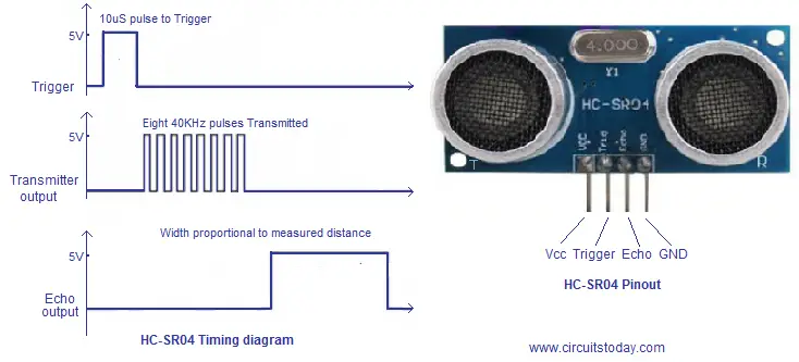
HC-SR04 ultrasonic ranging module.
HC-SR04 is the ultrasonic ranging module used here. HC-SR04 consists of an ultrasonic transmitter, receiver and necessary electronics for making it a stand alone system. The operating principle is very simple. It sends 8 pulses of 40KHz sound waves, and picks up the reflected wave. The time lag between the transmission and reception is measured and the distance is calculated from the equation D=TS/2. Where D is the distance, T is the time lag and S is the speed of sound. The output of the HC-SR04 will be a pulse whose width is proportional to the distance. From the datasheet, width of the output signal will be 58uS for a distance of 1cm. What we need to do is to just send a 10uS wide trigger signal to the trigger pin of the module and wait for the output pulse at the echo pin of the module. Timing diagram and pin out of the ultrasonic module is given below.
For knowing more about the HC-SR04 ultransonic module and its interfacing to 8051 microcontroller, go through this article. Ultrasonic range finder using 8051. Full circuit diagram of the ultrasonic water level controller is shown below.
Circuit diagram.
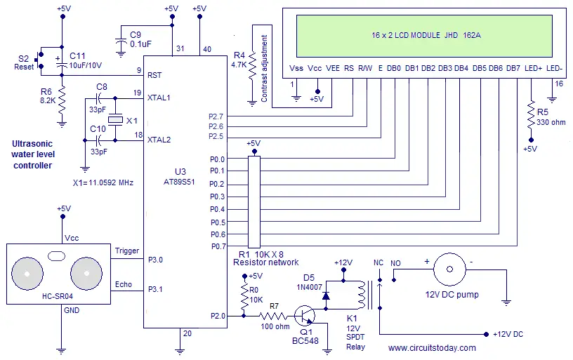
Trigger pin of the ultrasonic module is connected to P3.0 of the microcontroller. Echo pin of the module is connected to P3.1 of the microcontroller. Data lines of the LCD is module is interfaced through Port0 of the microcontroller. The control lines RS, RW and E of the LCD module are connected to P2.7, P2.6 and P2.5 pins of the microcontroller respectively. The pump is controlled using Port 2.0 of the microcontroller. The pump used here is a 12V automobile windscreen washer pump.Mains operated pumps will also go with this circuit but their current rating must match with the relay you are using.Anyway be careful to avoid the risk of electric shock while working working with mains operated devices.
Here the ultrasonic ranging module is placed on top of the tank facing the water surface. The water reflects the ultrasonic pulses emitted by the module.The module pics the reflected waves and also measures the time lag. The distance between the water surface and the sensor is calculated from the collected data and the module outputs a pulse whose width is proportional to the distance. The microcontroller reads the width of this output pulse and does necessary maths on it to get the distance. Here we can see that the water level is measured from top to bottom unlike most sensors which measure the level from bottom to top. This is done to make this device suitable for a wide range of depths. Since the sensor is placed on top of the tank we need to subtract the distance from the sensor to the water surface from the total depth of the tank in order get the level of water from bottom to top. Since different tanks have different depths the individual user has to measure the depth of the tank manually and alter the program with this data.
This problem is solved by measuring the level from top to bottom. Here the device switches ON the pump when the level falls below 20 cm from top and switches OFF the pump when the level rises to 5 cm from top. The level displayed on the LCD screen is actually the depth of the water surface from top. Tanks with depth up to 1.5 meters will go well with this project.
Program.
RS EQU P2.7                 ;equates RS to P2.7
RW EQU P2.6                 ;equates RW to P2.6
E  EQU P2.5                 ;equates E to P2.5
ORG 00H                     ;origin
      MOV DPTR,#LUT         ;move starting address of LUT to DPTR
      CLR P3.0              ;clears P3.0(output)
      SETB P3.1             ;sets p3.1(input)
      MOV TMOD,#00100001B   ;sets Timer1 as Mode2 timer and Timer0 as Mode1 timer
 MAIN:ACALL DINT            ;calls DINT subroutine
      ACALL TEXT1           ;calls TEXT1 subroutine
      MOV TL1,#200D         ;loads TL1 with start value
      MOV TH1,#200D         ;loads TH1 with reload value
      MOV A,#00000000B      ;loads A with all Zeros
      SETB P3.0             ;sets P3.0(trigger pulse)
      ACALL DELAY1          ;calls DELAY1 subroutine (1uS)
      CLR P3.0              ;clears P3.0
      HERE: JNB P3.1,HERE   ;loops here until echo is received
 BACK:SETB TR1              ;statrs Timer1
HERE1:JNB TF1,HERE1         ;loop here until Timer1 roll over occurs
      CLR TR1               ;stops Timer1
      CLR TF1               ;clears Timer Flag 1
      INC A                 ;Increments accumulator
      JB P3.1,BACK          ;jumps to label BACK if echo is still present
      MOV R7,A              ;saves accumulator to R7
      ACALL SPLIT           ;calls SPLIT subroutine
      ACALL LINE2           ;calls LINE2 subroutine
      ACALL LEVEL           ;calls LEVEL subroutine
      ACALL TEXT2           ;calls TEXT2 subroutine
      ACALL TEXT3           ;calls TEXT3 subroutine
      ACALL CHECK           ;calls CHECK subroutine
      JB P2.0,JUMP          ;jumps to label JUMP if P2.0 is set
      ACALL TEXT4           ;calls TEXT4 subroutine
      SJMP EXIT2            ;jumps to label EXIT2
 JUMP:ACALL TEXT5           ;calls TEXT5 subroutine
EXIT2:ACALL DELAY2          ;calls DELAY2 subroutine(1S)
      SJMP MAIN             ;jumps to label MAIN

CHECK:MOV A,R7              ;loads value of R7 to accumulator
      SUBB A,#20D           ;subtracts 20D from A
      JNC ON                ;jumps to label ON if carry flag not set(A>20D)
      ACALL OFF             ;else calls OFF subrotine
      SJMP EXIT             ;jumps to label EXIT
   ON:SETB P2.0             ;sets P2.0 (motor ON)
 EXIT:CLR CY                ;clears carry flag
      RET                   ;return from subroutine

OFF: MOV A,R7               ;loads value of R7 to accumulator
     SUBB A,#5D             ;subtracts 5D from A
     JNC EXIT1              ;jumps to label EXIT1 if carry flag not set(A>5D)
     CLR P2.0               ;else clears P2.0(motor OFF)
EXIT1:CLR CY                ;clears carry flag
      RET                   ;return from subroutine

DELAY1: MOV R6,#2D          ;loads R6 with 2D
LABEL1: DJNZ R6,LABEL1      ;loops here until R6 is 0
        RET                 ;return from subroutine

DELAY2:MOV R0,#15D          ;loads R0 with 15D
BACK1: MOV TH0,#00000000B   ;loads TH0 with start value
       MOV TL0,#00000000B   ;loads TL0 with start value
       SETB TR0             ;starts Timer0
HERE2: JNB TF0,HERE2        ;loops here until roll over occurs
       CLR TR0              ;stops Timer0
       CLR TF0              ;clear Timer Flag 0
       DJNZ R0,BACK1        ;loops the timer session 15 times for 1S delay
       RET                  ;return from subroutine

TEXT1: MOV A,#48H           ;ascii of "H"
    ACALL DISPLAY           ;calls DISPLAY subroutine
    MOV A,#32H              ;ascii of "2"
    ACALL DISPLAY           ;calls DISPLAY subroutine
    MOV A,#4FH              ;ascii of "0"
    ACALL DISPLAY           ;calls DISPLAY subroutine
    MOV A,#20H              ;ascii of " "
    ACALL DISPLAY           ;calls DISPLAY subroutine
    MOV A,#4CH              ;ascii of "L"
    ACALL DISPLAY           ;calls DISPLAY subroutine
    MOV A,#45H              ;ascii of "E"
    ACALL DISPLAY           ;calls DISPLAY subroutine
    MOV A,#56H              ;ascii of "V"
    ACALL DISPLAY           ;calls DISPLAY subroutine
    MOV A,#45H              ;ascii of "E"
    ACALL DISPLAY           ;calls DISPLAY subroutine
    MOV A,#4CH              ;ascii of "L"
    ACALL DISPLAY           ;calls DISPLAY subroutine
    MOV A,#20H              ;ascii of " "
    ACALL DISPLAY           ;calls DISPLAY subroutine
    MOV A,#43H              ;ascii of "c"
    ACALL DISPLAY           ;calls DISPLAY subroutine
    MOV A,#54H              ;ascii of "T"
    ACALL DISPLAY           ;calls DISPLAY subroutine
    MOV A,#52H              ;ascii of "R"
    ACALL DISPLAY           ;calls DISPLAY subroutine
    MOV A,#4CH              ;ascii of "L"
    ACALL DISPLAY           ;calls DISPLAY subroutine
    RET                     ;return from subroutine

 TEXT2:  MOV A,#63H         ;ascii of "c"
    ACALL DISPLAY           ;calls DISPLAY subroutine
    MOV A,#6DH              ;ascii of "m"
    ACALL DISPLAY           ;calls DISPLAY subroutine
    RET                     ;return from subroutine

 TEXT3:MOV A,#20H           ;ascii of " "
       ACALL DISPLAY        ;calls DISPLAY subroutine
       MOV A,#4DH           ;ascii of "M"
       ACALL DISPLAY        ;calls DISPLAY subroutine
       MOV A,#6FH           ;ascii of "o"
       ACALL DISPLAY        ;calls DISPLAY subroutine
       MOV A,#74H           ;ascii of "t"
       ACALL DISPLAY        ;calls DISPLAY subroutine
       MOV A,#6FH           ;ascii of "o"
       ACALL DISPLAY        ;calls DISPLAY subroutine
       MOV A,#72H           ;ascii of "r"
       ACALL DISPLAY        ;calls DISPLAY subroutine
       MOV A,#20H           ;ascii of " "
       ACALL DISPLAY        ;calls DISPLAY subroutine
       RET                  ;return from subroutine

 TEXT5: MOV A,#4FH          ;ascii of "O"
        ACALL DISPLAY       ;calls DISPLAY subroutine
        MOV A,#4EH          ;ascii of "N"
        ACALL DISPLAY       ;calls DISPLAY subroutine
        RET                 ;return from subroutine

 TEXT4:MOV A,#4FH           ;ascii of "O"
       ACALL DISPLAY        ;calls DISPLAY subroutine
       MOV A,#46H           ;ascii of "F"
       ACALL DISPLAY        ;calls DISPLAY subroutine
       MOV A,#46H           ;ascii of "F"
       ACALL DISPLAY        ;calls DISPLAY subroutine
       RET                  ;return from subroutine

SPLIT:MOV B,#10D            ;loads 10D to B
      DIV AB                ;divides A with B
      MOV R3,B              ;saves the remainder to R3 (3rd digit)
      MOV B,#10D            ;loads 10D to B
      DIV AB                ;divides A with B
      MOV R2,B              ;saves the remainder to R2 (2nd digit)
      MOV R1,A              ;saves the quotient to R1 (1st digit)
      RET                   ;return from subroutine

LEVEL:MOV A,R1              ;moves R1 to A (1st digit)
      ACALL ASCII           ;calls ASCII subroutine
      ACALL DISPLAY         ;calls DISPLAY subroutine
      MOV A,R2              ;moves R2 to A (2nd digit)
      ACALL ASCII           ;calls ASCII subroutine
      ACALL DISPLAY         ;calls DISPLAY subroutine
      MOV A,R3              ;moves R3 to A (3rd digit)
      ACALL ASCII           ;calls ASCII subroutine
      ACALL DISPLAY         ;calls DISPLAY subroutine
      RET                   ;return from subroutine

 DINT:MOV A,#0CH            ;display ON cursor OFF
    ACALL CMD               ;calls CMD subroutine
    MOV A,#01H              ;clear display screen
    ACALL CMD               ;calls CMD subroutine
    MOV A,#06H              ;increment cursor
    ACALL CMD               ;calls CMD subroutine
    MOV A,#80H              ;force cursor to the begining of 1st line
    ACALL CMD               ;calls CMD subroutine
    MOV A,#3CH              ;activate 2nd line
    ACALL CMD               ;calls CMD subroutine
    RET                     ;return from subroutine

LINE2:MOV A,#0C0H           ;jump to 2nd line position 0
    ACALL CMD               ;calls CMD subroutine
    RET                     ;return from subroutine

CMD: MOV P0,A               ;moves A to P0
    CLR RS                  ;clears RS pin of LCD
    CLR RW                  ;clears RW pin of LCD
    SETB E                  ;sets E pin of LCD
    CLR E                   ;clears E pin of LCD
    ACALL DELAY             ;calls DELAY subroutine
    RET                     ;return from subroutine

DISPLAY:MOV P0,A            ;moves A to P0
    SETB RS                 ;sets RS pin of LCD
    CLR RW                  ;clears RW pin of LCD
    SETB E                  ;sets E pin of LCD
    CLR E                   ;clears E pin of LCD
    ACALL DELAY             ;calls DELAY subroutine
    RET                     ;return from subroutine

DELAY: CLR E                ;clears E pin of LCD
    CLR RS                  ;clears RS pin of LCD
    SETB RW                 ;sets RW pin of LCD
    MOV P0,#0FFH            ;sets P0 as input
    SETB E                  ;sets E pin of LCD
    MOV A,P0                ;moves P0 to A
    JB ACC.7,DELAY          ;jumps back to label DELAY if ACC.7 is set
    CLR E                   ;clears E pin of LCD
    CLR RW                  ;clears RW pin of LCD
    RET                     ;return from subroutine

ASCII: MOVC A,@A+DPTR       ;over-writes A with ascii code of data in A
       RET                  ;return from subroutine

LUT: DB  48D                ;ascii of "0"
     DB  49D                ;ascii of "1"
     DB  50D                ;ascii of "2"
     DB  51D                ;ascii of "3"
     DB  52D                ;ascii of "4"
     DB  53D                ;ascii of "5"
     DB  54D                ;ascii of "6"
     DB  55D                ;ascii of "7"
     DB  56D                ;ascii of "8"
     DB  57D                ;ascii of "9"

    END                     ;end statement
About the program.
P3.0 of the microcontroller is used for triggering the HC-SR04 ultrasonic module and P3.1 of the microcontroller is used for receiving the echo signal. Both timers of the 8051 microcontroller are used in this project. Timer1 is operated in MODE2 (8 bit auto reload) and Timer0 (16 bit)is operated in MODE1. A 1uS wide trigger signal is given to the trigger pin of ultrasonic module and the microcontroller waits for the echo signal at the echo pin of the module. Echo pin of the module and P3.1 of the microcontroller are connected. The status of this pin is polled using JNB instruction. When ever a valid echo signal is received at this pin Timer1 is started. The timer counts from 200D to 255D (55 counts) and then it roll overs.After each roll over the echo pin is checked again and the timer is restarted if there is any echo signal present. For each roll over, the accumulator is incremented and this cycle is repeated until the echo vanishes.
From the datasheet of HC-SR04 it is clear that a 58uS wide echo pulse denotes 1cm. Here we are actually counting the number of 58uS wide blocks in the eco signal and the count directly indicates the distance in cm. Since the microcontroller is clocked using a 12MHz crystal 55 count means 55uS.The other instructions executed during each timer cycle cost around 3uS and so in total 58uS is elapsed during each timer cycle. The number of timer cycles ie; the count in accumulator indicates the distance in cm.
Then necessary operations are done on the accumulator value and it is displayed on the LCD screen.Here the program is set to switch ON the pump when the level goes below 20cm (low level) from top and to switch OFF the pump when the level rises to 5cm (high level)from top. The switch ON condition is identified by subtracting 20D from the accumulator value.If the carry flag is not set, it means that the water level is below 20cm from top and the motor is switched ON.
If carry flag is not set, OFF subroutine is called. In this subroutine, 5D is subtracted from the value stored in accumulator and the status of carry flag is checked using JNC instruction. If carry flag is not set, it means that the level is below 5cm from top and the pump remains ON. If the carry flag is set it means the level is above 5cm from top and the pump is switched OFF.
The pump is controlled through P2.0 of the microcontroller. The status of this pin is checked using JB instruction. If this pin is high, that means the pump is ON and status message ” Motor ON” is displayed on the LCD. If the P2.0 pin is low that means the pump is OFF and the status message “Motor OFF” is displayed on the LCD screen. Read this article Interfacing LCD display to 8051 microcontroller for understanding more about the display interfacing part.
16 Comments
Should we use AT89C51 or AT89S52 microcontroller for this circuit?
Water bottle zakan on force measure and display Reding using microcontroller.
Required
What is the use of X1 and how can we connect this part to the circuit…Please reply I am not understanding X1
Dear,Please upload the HEX file
AKAIK yo’uve got the answer in one!
i tried creating HEX file using the source code but got this message…source.c(1): error C129: missing ‘;’ before ‘EQU’
Target not created.
Build Time Elapsed: 00:00:00.
what could be the problem? and how can i solve it
I finished circuit and programmed 89s51 but how to know why its not working
I completed the circuit assembly and burned the above program in 89s51 but nothings seems to be working …
Please give the code in c-language
What changes has to be made if, I want to change the level of water detection in the program.
Please reply.
it is too much interesting and likey project with complete description!!
I think you can not use it for measuring depth of water tables underground because the trigger signal of this sensor is not capable of penetrating the earth crust. The above circuit is designed for reflection of 40KHz waves in air medium.
I need help.. can I use At89s52 in this circuitry?
Yes You can use with a little change in programming!
An EXCELLENT system for measuring depth of water tables under-ground.
Can we know whether this circuit has been tried, tested and found working satisfactorily ?
On confirmation, we wish to assemble the same and give our feedback.
What is the source for the ultra-sonic modules ?
We shall be grateful for a reply.
B S Murty.
which simulator is used to simulate this project………???