USB LED Lamp Circuit
Description
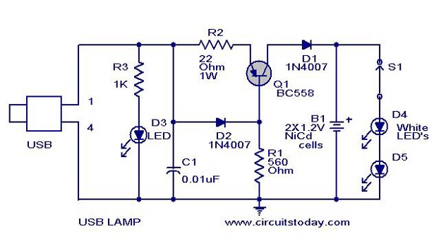
Here is a simple USB powered lamp that can be used to light your desktop during power failures. The circuit operates from the 5 Volt available from the USB port. The 5V from the USB port is passed through current limiting resistor R2 and transistor Q1. The base of transistor Q1 is grounded via R1 which provides a constant bias voltage for Q1 together with D2. The diode D1 prevents the reverse flow of current from battery. C1 is used as a noise filter. Two white LED’s are used here for the lamp, you can also use a 2 V torch bulb instead of LED’s. LED D3 indicates connection with USB port.
USB LED Lamp Circuit Diagram with Parts List

| Component | Specification |
|---|---|
| USB | |
| Q1 | BC558 |
| R1 | 560 Ohms |
| R2 | 22 Ohms |
| R3 | 1K |
| C1 | 0.01uF |
| D1, D2 | 1N4007 |
| D3 | LED |
| D4 | White LED |
| Battery | 2x1.2V (Ni-Cd Cells) |
| Switch | S1 |
Notes
- USB port is only able to provide up to 100 mA current. So don’t overload the circuit with more no of LED’s.
- Before wiring the circuit confirm the positive and ground leads of USB by a multimeter.
- Switch S1 can be used to turn on the lamp.
We have more interesting USB Circuits that you may like to see;
1. USB Sound Card

2. 12 Volt from USB Port

24 Comments
i didnt understand how it works when i draw this circuit in multisim we didnt got the output any one pls explain this
if i don’t want the battery backup than now i have to just remove the battery only or i have to do any other externely changes in ckt
Hi Deep connect pin 1 of usb to 47 ohms 1/4 watt resistance connect to anode of 2nos white LEDs and their cathode to Pin 4 of USB pin.
how approximatery long can our rechargeable battery sustain the leds
LOLzzzz, if you still need to connect a external battery why to put it in USB than. Make a LED torch light instead..
Hi
thanks for the Circuit
can u Please Share the Datasheet for This Circuit as given in
5V to 12V converter …
It works when I give 5V power supply but it doesnt work when I plug into the usb port
I have made the above usb lamp.
The lights cannot be turned on when I use 2.4V rechargable battery, however, it is on when I use 3.6 recharable battery.
Besides, when I plug the usb lamp into computer’s usb port, it doesnt work..why is it like that?
and thanks for your design =)
Hi Kailash add one more 1N4007 in series with D2 then the constant current output at Q1 collector will be 30mA . Two Nicad cells fully charged voltage will be 2.64 volt. Connecting the LEDs in series the requirement will be 5.2 volts, which 2 cells cannot supply hence they will not glow. Connect both the LEDs in parallel, then it will work as each requires minimum 2.6 volt to glow. Rechargeable battery is the back up for the LEDs during power failure. The above circuit is not meant for supplying USB voltage to computer during power failure.
how many diodes and rechargeable batteries in this diagram are required purpose ?
Where we hav to connect d usb? How desktop can b operated with 5volt battery used in dis circuit? Plz send me some reply.
you can’t connect the LED direct –without current limiting resistor–to the battery
Please tell me, why we use battery b1 in USb lamp circuit….?
battery B1 provides the back up power
Umm if the power is down.. is the computer also.., do not take me wrong, great idea and all.. but if the power goes out and by chance the phone line is still live take the lamp off the usb and use it on the phone line 😉
can you please explain farther the flow of this circuit in a USB lamp
hello. why is there the battery? back-up energy supply when computer is down?
THIS IS UBER pWNAGE
please where will i connect the 5v of the usb(usb lamp circuits)