Description.
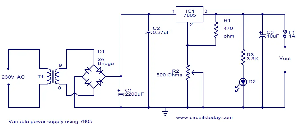
This circuit diagram shows you how to make a 5V to 12V variable DC power supply from a fixed 5V regulator IC 7805. This is attained by adding two resistors R1 and R2 as shown in figure. When the resistors R1 and R2 are added the equation for the output voltage of 7805 becomes Vout= Vfixed + { R2 [ (V fixed/R1) + Istandby] } ,where Vfixed=5V and Istandby=Vfixed/R1.By varying the POT R2 you can adjust the output voltage between 5V and 12V.
Notes.
- The circuit can be assembled on a vero board.
- T1 can be a 230V primary, 9V/5A secondary stepdown transformer.
- 7805 must be fitted with a heat sink.
- F1 can be a 1A fuse.


8 Comments
setau ane itu pakenya ic lm317 bukan 7085
How to fix the values of the capacitors ?
What is their use ?
C1 is the filter capacitor the thumb rule is 2200uF per amp at 100Hz. For 2 amps @ 50Hz is 10000uF. Etc. C2 is a HF decoupling capacitor to avoid HF instability. C3 is for reducing the output impedance of the power supply such that no instability in the connected load due to power supply common impedance effect.
Hi Jov 25volts will do
voltage rating for c1 and c2
quite naturally it will output only less than 7V. The power supply here is only 9V output. If you used a 14-18V supply then you will get all the voltages mentioned in the article. Even if you get the voltages out after inputting 12V plus, the whole idea of boost is defeated, especially when the current this contraption will eck out is a measly 100ma or less. This article is misleading.
Sorry bro.
I tried it gives 7v o/p not 12 or 9. I’ve varied R2 but o/p is still same.
It gives 3.4 3.6v at r1 and r2.
I’ve 1000uf,10uf. I think they are enough. Ckt is checked 5 times. Help needed guys.
Sorry to say but it won’t give o/p more than 7v.
It gives 3.4v+3.6v. I’ve varied R2 from 550 ohm to 100 ohm but o/p remains same.
I’ve made same ckt only capacitor 1000uF And 10uF.