Description.
Here is a simple water level alarm circuit using 555 timer that will produce an audible alarm when the water level reaches a preset level.The circuit can be powered of a 3V battery and is very handy to use.
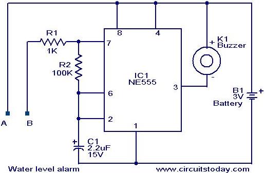
The circuit is based on an astable multivibrator wired around IC1 (NE 555).The operating frequency of the astable multivibrator here will depend on capacitor C1, resistances R1,R2 and the resistance across the probes A&B.When there is no water up to the probes,they will be open and so the multivibrator will not produce oscillations and the buzzer will not beep.When there is water up to the level of probes,some current will pass through the water,the circuit will be closed to some extend,and the IC will start producing oscillations in a frequency proportional to the value of C1,R1,R2 and the resistance of water across the probes.The buzzer will beep to indicate the presence of water up to the level of the sensing probes.
Circuit diagram with Parts list.
Notes.
- The circuit can be powered of a 3V battery.
- Assemble the circuit on a good quality PCB or common board.
- The probes can be made of two insulated copper Aluminiun wires.
- Place the probes at the position where you have to sense the level.
130 Comments
I’m trying this circuit…….
But I’m not getting the output ….
Can you help me with this?
Is it work only in electrolytic water?
How conductivity and amount of water affect the sensitivity?
please help me out.
Etched the board and built the circuit . It did not work for me , the buzzer is constantly on. fail.
what is the use of 555 timer ic and what is the role capacitor in water level indicator
Hello and thank you for this. I didn’t have a 2.2uF cap so I used a 1uF cap. I also tried using a 5v boost for the 3.7v battery and it seems to work nicely. More sensitive. I also used a double stranded 28 gauge wire for the probe/sensor by trimming a tiny bit of the wire jacket at the end so it works like a double contact sensor with water closing the circuit.
super
Can we use this ckt at 220v supply
For 220v, you must need a 3v eliminator transformer with a rectifier circuit.
Not advisable as you are dealing with water. If there develops a leakage to the circuit it may electrocute you, In circuits like this I would stick to dry batteries. Consumption will be low and the batteries will last a while because of intermittent usage.
Great post.
Hi, I need a circuit which sets an alarm when the probes are not in water. i.e the level of water is low. Is there a way how this circuit can be reversed please ?
can you help me with the block diagram of this circuit stating function of each block
What modification has to be done for a buzzer with higher sounds
With just 3 volts you may not get a big sound. Use higher voltage perhaps 6-9 volts and play around with the type of buzzer. Get a buzzer that has a tiny built in booster transistor in it and you can identify it because it has a black wire fir negative and red wire to be connected to positive side in this circuit diagram.
This circuit works perfectly.
I replaced buzzer with LED, the LED blinks when prob A & B are short circuited.
Thanks.
The circuit diagram shows that it is operating on a 3v battery. But i checked the datasheet of NE555. Its operating voltage range is from 4.5-18v. Will this circuit work on 3v voltage source?
It will work but with lesser sound. Perhaps, designed to be compact size with 2 AA sized dry cells. Yes! You can increase it to 9 volts and get a more powerful buzzer. It will surely work
how to do this project on simulink of MATLAB..??
Guys please help i have an project to submit this week…!!!
Its can be easily done on the bread board. Anyone let me know the procedure of working And I don’t no wat and how to work with pcb . Plz give me the complete details about pcb
It can be assembled on a standard IC PCB available in PCB shops. The operation of this circuit is, a standard timer IC NE555 with Piezo beeper. once the water level touches the probe the timer will start oscillating and beeper will beep. Once water level goes bellow it will stop.
view this site for the PCB type
http://www.smcelectronics.com/perf.htm
If you are good with soldering you can assemble this simple circuit just by using a single strength copper wire directly connecting as it is in the diagram without PCB or breadboard. As the 555 ic is sensitive to too much heat from the soldering iron, I would buy a IC holder. Fix the IC last after everything is done. You can nicely place the whole circuit in a neat little plastic box. Make sure the soldered wires do not touch each other.
I m new to projects
… Tell me briefly about this ckt… Can buzzer be replaced with LED? Reply me..
plz…
yes buzzer can be replace by LED.
2.2 uf wont do the job
Replace it with 0.01 uf
Other values ok
Really thanks for making the correction. I’m breaking my head with the output. You gave the right answer and helped me a lot.
The capacitor value is used to determine the frequency pitch. It works with the 100K resistor as a RC network. By using a higher value capacitor the sound will be more bass and using a smaller capacitor the sound pitch will be sharper and more treble.
yes this project works.. i made a mini project y collecting this information.
this project is so simple that i made it in 15min.with good result..!
after connecting all the equipments as per the circuit diagram.,then finally a two wires are connected to the buzzer.And I kept that in water glass. and started pouring water when the water reached wires(connected to probes),the buzzer started sound.
FINALLY… Water level alarm circuit started working.. I succesfully completed my mini project.
THANK YOU..
Can anyone explain abt connections
sir, i want to know that how much cost will be to make this experiment…and suggest me more easy projects which i can perform easily. and respective prices also….mind it sir that i m a b.tech 1st year student… ok bye sir .. good bye… reply must sir… i m waiting for your suggestion….for this i shall be highly greatful to you..
one thing more sir..
i m very weak in progromming languages ,,, such as C C++ .. oops etc..
please tell me the importance of programming and could i be a good engineer without commanding in this subject,,,,okk see u soon sir byree…ebye
the work done by this circuit is simply achieved by using (probe, battery, buzzer)but i like this….
is this going to work??????????????????/
hi i want knw d circuit wrkng n d place wer v get these components… n is pcb neccesary?
hi frnds…plz help me out to do ths project.. i want d details abt d buzzer n d place wer v get all these components in bng?
We are working of pcb designer .(altium and protel softwere).if you want requitement please contact sir further detail contact my id please
mail.id:
pcbaltium7@gmail.com
hi frnds.. i wud lyk to do ths project. but im new to projects..so plz help me out. is pcb necessary to connect the ckts n frm wer do i get all the required components in bng? is sp road rite place?
Hi, i’m very new to do projects, this 1’l b first. So can u plz send me the whole things required to complet this project lik pcb design, software if necessary, any precautions to take, plz plz
for simple ckt design there is no need of software. implement this circuit in breadboard then implement in the printed circuit board(pcb). circuit design is easy when you learn so learn as much as you can,
have a good day
does this circuit require any particular buzzer??? if yes, which buzzer???can i replace the buzzer with led????
I want some applications of water level alarm
Hi… Need some help here, please… Is it possible for this circuit to work “in reverse”?… Meaning, I need the buzzer to sound ONLY when both probes are NOT in contact with water… Like a low water level alarm, with both probes posicioned in the BOTTOM of the tank… If possible, what changes have to be done in this circuit?… Thanks!
Hai i have joined to do this project and hope that do this work
Just now i purchased every thing. I am new to electronics, don’t have any background in electronics, just for hobbies i am doing this project, plz help i am cofused regarding the IC 555 terminal, in diagram it showing 1,2,3,4,5,6,7,8 how to locate the nos in IC plz help and one more thing can solder resister in any direction regards.
Please go through the datasheet of NE555. From the top (from the component side)it will be anticlockwise from the dot or the index shown as pin number 1 and count anti clockwise. (from the soldering side it will be clockwise)
This is one of very useful projects in real life also. Very interesting to read. I have also seen another circuit diagram on the same concept. If anybody interested, visit http://www.electronicshub.org/water-level-alarm-using-555-timer/
This mini project is very intresting, andmail me “WATER LEVEL ALARM CIRCUIT”
Hay i also choose this project. Can u help me to complete this project ?
hey who can help me with the calculation procedures i am really new at this.
this is nt enough info !!!!!!! we reqire lots bcoz we r frm MU !!!!
instead of 1kilo ohm&100 kilo ohm resistors we use another resistors what will happens.
capacitor 2.2 uf replaced by 10uf what will happen
Hi Narendar 1K, 100K and 2u2 desides the frequency of oscillation. Refer NE555 manual.
hhhhhow can i replace buzzer ?
hello sir you have used here this ic as astable mode hence the buzzer can beep until the probes in contact with water am I right?
i,m going to do this as my project.pls send me a mail abt the whole process
and can u convert the 1k &100k resistance to ohm .or do we get in k in shops.and where do we get the components,
thanks
will it be suitable to sense the overflow of our tank
I haven’t executed this circuit but i have a doubt. when the supply is given to the circuit won’t the buzzer work immediately giving out the noise signal? how should i avoid this problem?
hi sruthi ic pin 3 will be high. once a and b are linked by water it will go high and low as per r1, r2 and c1. hence the electronic sounder will bleep whenever pin no 3 goes low.
i done this project but the problem is that even the probes are not upto the water level the buzzer will ring…means as soon as i give the supply the buzzer will ring . pls help me
the crkt diagram sketched above is wrong.don’t give supply to buzzer but to jst pin no.8&4,which are shorted ground capacitor c1 so it will produce frequency above 60Hzs which is necessary for buzzering
@Kedar_Vaze PLZZZ give me some more imfo abt this problem …. means… tell mee where i can connect the buzzer then ..and from where to where i should give the power supply to the circuit… .. m confused if we dont give the power supply to the buzzer..then where will b the positive terminal of the buzzer b connected ..tell me the solution pleasee.. 🙁
Where we have to use the buzzer
I will try it
if i use 2.2 microferade capasiter c1 50v instead of 2.2 microferade capasiter c1 15v
i need a brife information about “Water level alarm” .Its introduction,circuit diagram,procedure,function,merits & de-merits and its conclusion…Plz reply
me as soon as possible,plz plz plz……….
i dont have any . sorry ……
i too am finding……
can u plz send me whole process
we r tryng it ……………..
tell me the procedure details briefly
hey buzzer is not available ,can i use an LED instead ? plzzz help ASAP
Can u mail me full description on this project..?….plz
give me full specification and the cost of that project.water level alarm ckt.
ala doba shu kare 6??
Why you are using 555 timer?
Can simple circuit is use (1 resistor,capacitor,battery,buzzer)?
Is the various type of buzzer is sell? & according to which type?
please tell & guide me
I used my mobile bettery 3.7volt.
anyone send me report of this circuit plz plz……
i make this project and the buzzer give output tet tet…:p
How to buy PCB board for this circuit.plz advise
i have used 5V power supply.. the circuit works.. have tested it using led in place of buzzer.. but d buzzer is not producing any sound.. can u please help;.. whats is wrong with d buzzer and how to make it work?
Hi,
Which buzzer can be used for this circuit i mean K1 buzzer. Please let me know the specification of it.
a nice mini project
well done priyanka for posting this
luv u
It workssssssssssss…………..
thanks!!!!!!!!!!!!!!!!!!
According to the above circuit…i have a problem… the probes are not connected but still the buzzer is producing sound.. infact the circuit is correct according to the given diagrame.. plzz tell me wat should i do to make it correct .. !! need a solution ASAP.. !!
From the above comments i saw that…the circuit is nt correct..one of them says.. tht i should nt connect the buzzer to the power supply…but the confusion is that then from where to where ill connect the buzzer and the battery.. !! .. .Plzzz help me out.. 🙁
can we use 12 volts battery and can get an output of 12 volts at the time of circuit activation , i want to use sounder of 12 volts at activation of circuit.
Hi
Is there may be any problem if I use above circuit with 9volt battery if so what are the changes required? I have already implemented this circuit for my home over head water tank. It is working fine but the loudness of the buzzer is poor as the water tank and the circuit having distance almost 60 feet. Also I would not like to change the battery frequently what is the solution for that.
Regards
this circuit is not working guys plz give me some sugessions to work
i need complete details regarding this i need how to make water level indicator.it`s very helpful for students.plllllllllllllz do that
when the supply is given,the buzzer starts beeping.even when the probes arent in the water.!!!can u please give the solution for this.i also needed the design for this circuit.so can u please mail it to me?
the wire which is connected to buzzer is if short then the buzzer is beeping. check it..
The same problem goes with mee too… the probes are not connected but still the buzzer is producing sound.. infact the circuit is correct according to the given diagrame.. plzz tell me wat should i do to make it correct .. !! need a solution ASAP.. !!
I want the detailed explantn abt this and i liked it and i need it urgently!!!!!plz do it as soon as possible
sir,
u give me a using compudent.onents…….in my id ok……i wait…i am iiet st
this ckt is fail in working coz when v give supply d buzzer starts buzzing with out touching d probes in water
aby solution plz tell me
send me details to my mail id
The description is too short i think…Can you give it little bit elaborate…
with c1=2.2uF , R1=1k and R2=100k as shown in the circuit the buzzer does not and cannot work ! c1 must be 2,2 or 22 nF. I wonder why no one realized this….
how it is apllicable
hi!This circuit will work only when the water level is upto the probes rite..can we modify ths circuit by making it beep both the times when the water is at 1/4th level and when it is full.So that it will be easy for me to on and off the switch.plz reply ..
setup ha
hi frnds pls give me idea to do this. by using bread board haaaa….
I use this to my project…I hope that it work properly..
its working good
this project works!guys need some help what buzzer should i use?i tried to conect it to an alarm clk coz i dont have any buzzer but the prob is the alarm clk keeps on sounding even theres no contact in the probes.
@ Deepesh Shah Connect a 0.01uF capacitor between pin 5 and ground (-ve of the battery )
mail me any latest news or innovation on circuit
In this circuit where pin no.5 is not shown. So to run the circuit where it should be connected.
Hi Seetharaman, yr Idea has been of great help for 15 days.
Now the ends of the wire that I dipped in the Water tank have
sulphated and do not conduct. After every 20-25 days I need to
clean the ends of the wire in the water tank. Pls suggest some other sensors which need no cleaning.
Thanks
Hi Hafeez pin no5 is not used and not required for this application.
wr is pin numbr 5 in ic pls tell me i want to do it in 2hr nw
Hi Bijay 2.7 to 12 volt music generator modules are available you can use one of them.
Thanks to seetharaman, the project is completed i have connect the 3-24v buzzer its not working, then to test the alarm i connect a 3v bulb in place of buzzer. i notice that the light is flashing ( is it ok flashing of bulb). can u suggest what kind of buzzer should i purchase,
Hi Bijay you cxan use resistance in any direction as they have no polarity like diodes and electrolytic capacitors. regarding NE555 pin connection refer following document in the out line it is shown clearly in the numbers will increase in anticlockwise direction as you view from the IC identity – screen printed / engraved side.
http://www.fairchildsemi.com/ds/LM/LM555.pdf
Seetharaman thanks for the help.
just now i purchased everything,, i m new to electronics, don’t have any background in electronics, just for hobbies im doing this project,
pl help i m confused regarding the IC555 terminal, in diagrams it showing 1.2.3.4.5….8 how to locate the nos in IC
pl help. and 1 more thing can solder resister in any direction,
Regards
Hi Bijay normal mobile chargers voltage lies between 5 to 7 volt can be directly used as the IC can operate up to 15 volts.
hi all. instead of 3v batteries, i would like use transformer of 3volts. pl let me know how to built that 3volt AC-to DC, can i use mobile phone charger for that..
Hiiiiiiiiiiiiii friends this ckt is working try this
Where is the parts list
Hi Neenoo it is 3volt DC. you can use a single lithium battery 123 or 2nos 1.5 volt cells in series. i think ac batteries are yet to be invented.
ia it an AC BATTERY OF 3V OR A DC BATTERY?
it helped our student to get some ideas for the science exhibition that is taking place in our school…. thanks a lot…. please mail me/…
sir i need a simple circuit daigram for my science project please help me within 15 aug please reply on my mail immidiately anyone please
Hi Patrick you can use 5amp house wiring wire 2 runs(1/18wire). You can use 5 volt power pack, which is standard these days for charging mobile phones.
The tank at my place is located at 60ft above. I live at ground level.I want to connect 2 copper wires from ground to tank. but can 3 volts battery be replaced with electrical power circuit. Thanks
if you are not able to hear the buzzer sound, then put only the sensors in the tank and connect it with rest of the circuit via the pipes which bring water to your home ,if they are made up of metal.
please give the parts related information and their cost
how to make this suitable for multi level indicating . .
give information on Water level alarm circuit project
which part of this ckt is sensor part?pls,reply me..thanks..
regards
the circuit is working fine.but the problem is our water tank is kept at a height of 20-25 feet.the audibility of buzzer is upto 10 feet only.how can i improve the buzzer sound. please suggest me necessary changes to be made to this circuit ?
the best solution is to keep the sensor part only in the tank and rest of the circuit in some place where you can easily hear the alarm.Connect the both parts by using wires.That is what i have done.
mail me any latest news or innovation on circuit
mail me any latest news or innovation on circuit
yes o