Water level controller using 8051.
A water level controller using 8051 is shown in this article. A lot of water level controller projects have been published in this website but this is the first one based on a microcontroller. This water level controller monitors the level of the over head tank and automatically switches on the water pump when ever the level goes below a preset limit. The level of the over head tank is indicated using 5 LED’s and the pump is switched OFF when the over head tank is full. The pump is not allowed to start if the water level in the sump tank is low and also the pump is switched OFF when the level inside the sump tank goes low during a pumping cycle.
We are selling a Project Kit for this Water Level Controller which can be bought from our Online Store. The project kit is a modified version of the project shown above. This Water Level Controller project kit uses 4 float switches to measure water level. The status of water level in the tank and status of the motor is displayed using an LCD module. This system monitors the water level of the tank and automatically switches ON the motor whenever tank is empty. The motor is switched OFF when the overhead tank or container is FULL.
The use of float switches makes the circuit rugged and ensures a maintenance free operation over a very long period of time. The project kit is available in plug and play form and do it yourself form. A 12-0-12 mains transformer is also available with the kit and it is not shown in the figure below.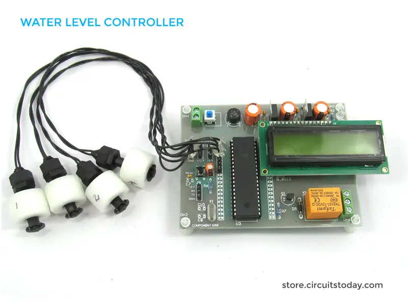
Main article continues…………….
The level sensor probes for the overhead tank are interfaced to the port 2 of the microcontroller through transistors. Have a look at the sensor probe arrangement for the overhead tank in Fig1. A positive voltage supply probe goes to the down bottom of the tank. The probes for sensing 1/4, 1/2, 3/4 and FULL levels are placed with equal spacing one by one above the bottom positive probe. Consider the topmost (full level) probe, its other end is connected to the base of transistor Q4 through resistor R16. Whenever water rises to the full level current flows into the base of transistor Q4 which makes it ON and so its collector voltage goes low. The collector of Q4 is connected to P2.4 and a low voltage at P2.4 means the over head tank is not FULL. When water level goes below the full level probe, the base of Q2 becomes open making it OFF. Now its collector voltage goes high and high at P2.4 means the tank is not full. The same applies to other sensor probes (3/4, 1/2, 1/4) and the microprocessor understands the current level by scanning the port pins P2.4 ,P2.5, P2.6 and P2.7. All these port pin are high (all sensor probes are open) means the tank is empty.
Port pin P0.5 is used to control the pump. When ever it is required start pumping, the controller makes P0.5 low which makes transistor Q6 ON which in turn activates the relay K1 that switches the pump. Also the LED d6 glows indicating the motor is ON. LED D7 is the low sump indicator. When the water level in the sump tank goes low, the controller makes P0.7 low which makes LED D7 to glow. The circuit diagram of the water level controller is shown in the figure below.
Circuit diagram.

Program.
MOV P2,#11111111B // initiates P2 as sensor input

MOV P0,#11111111B // initiates P2 as the output port

MOV A,#00000000B

MAIN:ACALL SMPCK // checks the level of the sump tank

MOV A,P2 // moves the current status of P2 to A

CJNE A,#11110000B,LABEL1 // checks whether tank is full

SETB P0.1

SETB P0.2

SETB P0.3

SETB P0.4

CLR P0.0 // glows full level LED

SETB P0.5

LABEL1:MOV A,P2

CJNE A,#11111000B,LABEL2 // checks whether tank is 3/4

SETB P0.0

SETB P0.2

SETB P0.3

SETB P0.4

CLR P0.1 // glows 3/4 level LED

LABEL2:MOV A,P2

CJNE A,#11111100B,LABEL3 // checks whether tank is 1/2

SETB P0.0

SETB P0.1

SETB P0.3

SETB P0.4

CLR P0.2 // glows 1/2 level LED

LABEL3:MOV A,P2

CJNE A,#11111110B,LABEL4 // checks whether tank is 1/4

SETB P0.0

SETB P0.1

SETB P0.2

SETB P0.4

CLR P0.3 // glows 1/4 level LED

JB P0.6,LABEL4

CLR P0.5 // switches motor ON

LABEL4:MOV A,P2

CJNE A,#11111111B,MAIN // checks whether tank is empty

SETB P0.0

SETB P0.1

SETB P0.2

SETB P0.3

CLR P0.4 // glows EMPTY LED

JB P0.6,MAIN // checks whether sump is low

CLR P0.5 // switches motor ON

SJMP MAIN

SMPCK:JB P0.6,LABEL5 // checks whether sump is low

SETB P0.7 // extinguishes the sump low indicator LED

SJMP LABEL6

LABEL5:SETB P0.5 // switches the pump OFF

CLR P0.7 // glows sump low indicator LED

LABEL6:RET

END
Related Projects
Moisture Sensing Automatic Plant Watering System – is an interesting project for hobbyists and students alike. This project is designed as a DIY automatic plant watering system based on soil moisture. Soil moisture is sensed using YL69 moisture sensor and 8051 microcontroller is used to interpret the sensor data and turn ON/OFF a motor pump for watering.
201 Comments
Can you give me a PCB layout of this circuit
Can you please tell me the name of all the components that are used to build water level indicator using 8051 microcontroller ?
I am going to prepare a project over this topic so kindly tell me as soon as possible. I highly need instructions about this.
Also where can I get all these components from ?
Thank you
I want this project kit of water level controller using 8051, how can l buy it and deliver to me
can we use it for 3 phase ac motor plx reply
Dear Sir , Kindly inform me how can I use the project kit without Sump Tank.
Waiting for your replay
MOV P2,#0FFH // initiates P2 as sensor input
MOV P0,#000H
MOV P0,#0FFH // initiates P2 as the output port
MOV P2,#000H
SETB P3.0
CLR P3.0
CLR A
MAIN:SJMP SMPCK // checks the level of the sump tank
LEVEL:MOV A,P2 // moves the current status of P2 to A
CJNE A,#11110000B,LABEL1 // checks whether tank is full
SETB P0.1
SETB P0.2
SETB P0.3
SETB P0.4
CLR P0.0 // glows full level LED
ACALL STOP_PUMP
LABEL1:MOV A,P2
CJNE A,#11100000B,LABEL2 // checks whether tank is 3/4
SETB P0.0
SETB P0.2
SETB P0.3
SETB P0.4
CLR P0.1 // glows 3/4 level LED
ACALL STOP_PUMP
LABEL2:MOV A,P2
CJNE A,#11000000B,LABEL3 // checks whether tank is 1/2
SETB P0.0
SETB P0.1
SETB P0.3
SETB P0.4
CLR P0.2 // glows 1/2 level LED
SETB P0.5
LABEL3:MOV A,P2
CJNE A,#10000000B,LABEL4 // checks whether tank is 1/4
SETB P0.0
SETB P0.1
SETB P0.2
SETB P0.4
CLR P0.3 // glows 1/4 level LED
ACALL STOP_PUMP
LABEL4:MOV A,P2
CJNE A,#00000000B,MAIN // checks whether tank is empty
SETB P0.0
SETB P0.1
SETB P0.2
SETB P0.3
CLR P0.4 // glows EMPTY LED
ACALL START_PUMP // switches motor ON
SJMP MAIN
SMPCK:JB P3.0,LABEL5 // checks whether sump is low
CLR P0.7
SETB P0.5
MOV R0,#0FFH
SJMP LEVEL
LABEL5:MOV R0,#000H
SETB P0.7
SJMP LEVEL
START_PUMP:CJNE R0,#000H,L1
CLR P0.5
RET
STOP_PUMP:SETB P0.5
L1:RET
END
The connection diagram needs to be modified at some regions.
Can anyone send me the correct coding please…..
Please anybody can me send layout
error c129: missing before target not created
can u please tell us which kind of pump r the motor we need to use
Pls sir I need details information about this project
how can this project be improved to work as river flood detector
SIR I HAVE IMPLEMEMNTED THE CIRCUIT BUT WE CANT GET OUTPUT . PLEAS HELP ME OUT. I THINK THERE IS A AN ERROR IN PROGRAMME.
sir instead of 80s51 shall we use at89s52 sir i kindly requesting to you please send at89s52 ic program for this water level controller project
can we use 89c52 instead of 89s51….
sir I want lcd indication program
i need to use 5v 220ohm relay???this cct is ok??
Sir i do automatic water level controller Using 8052 (at89s52) as per ur circuite but program is not working,Please help me and send me correct program.
everything is correct but the sensor is 2.0,2.1,2.2,2.3
this program is not working
Here is the program in c for above circuit, it’s as simple as it can be, easy to under stand.
#include
#define led_full P1_7
#define led_tbf P1_6
#define led_obt P1_5
#define led_obf P1_4
#define led_empty P1_3
#define pump P1_1
#define sump P0_0
#define led_sump P1_2
#define tank_full P0_7
#define tank_tbf P0_6
#define tank_obt P0_5
#define tank_obf P0_4
void main(){
while(1){
int i = 0;
if(tank_obf == 1 && sump == 0)
pump = 0;
if(tank_full ==0 || sump == 1)
pump = 1;
if(sump == 0)
led_sump = 0;
else
led_sump = 1;
if(tank_obf == 0)
i = 4;
if(tank_obt == 0)
i = 3;
if(tank_tbf == 0)
i = 2;
if(tank_full == 0)
i = 1;
switch(i){
case 1:
led_full = 0;
led_tbf = 0;
led_obt = 0;
led_obf = 0;
led_empty = 1;
break;
case 2:
led_full = 1;
led_tbf = 0;
led_obt = 0;
led_obf = 0;
led_empty = 1;
break;
case 3:
led_full = 1;
led_tbf = 1;
led_obt = 0;
led_obf = 0;
led_empty = 1;
break;
case 4:
led_full = 1;
led_tbf = 1;
led_obt = 1;
led_obf = 0;
led_empty = 1;
break;
default:
led_full = 1;
led_tbf = 1;
led_obt = 1;
led_obf = 1;
led_empty = 0;
}
}
}
note: kindly use the same port numbers used in this program.
first line is
#include
the program using C+ or C++. Thanks
Sorry. Actually, I’m asking not informing 🙂
on which application i should run the code.
plz tell me
sir i want diy kit of this model
hi sir your automatic water level controller program not executed in programmer it`s says errors in your program
Please send me correct program for automatic water level control using AT89S51. micro controller
Thank you sir
Sir i want to do automatic water level controller Using 8051 (at89s51)
Please help me and send me program
Hi,
Just me going through the diagram thought to myself that it could be useful to get a list of components with exact details, am new to it so quite challenging that is for me now, for example that X1 is 11.2MHz its only specification ?
And one more thing, does the relay has to be 200ohms ? hard to find one, biggest I seen in this voltage is 170 and out of stock at the moment, available 67ohm, is there way around, let me know ASAp please.
Jac
X1 is a crystal component
Can anyone tell me how does this motor works ?
Hi areeb to know complete process of automatic water level controller process visit my link
Sir, I constructed this circuit and its working fine. But I am worried about power supply circuit, will it be able to work 24×7 the whole year? And which is better, using a transformer or a smps power supply along with voltage regulator?
Hiii can you plz send me full details about this project,especially the program to burn..plzzz
Hello can you please mail me the perfect code with the output.Thanks
Pls,i want to carry out this project help me with materials.Thank you,Sir.
Hello….
I’m newbie in microcntrol.
I using reads51.
Why that program is not correct?
Always at ” MOV P0,#11111111B // initiates P2 as the output port “.
i will like to carry out this project myself,please can i get more matrials this.thanks
can u provide me with matlab code. send to my email thank u 🙂
can u send me the proteus view of this circuit? plz.
Can anyone plzz send me the correct program file for this project because given program is not working.
Thanks,
Hiren
i need afull project on this title with a ckt diagram
sir making total kit all are ok sump,motor,leds,and relay but
over head tank sensors,leds not working
pls give me solutions pls sir
pls give me reply
pls sir i have make total kit but not responding over head tank
xtal 11.0592 pls rectify this
sir yours 8051 projects are very nice. But i have some doubt. How to program my microcontroller plz rly answer
you need a programmer to program the microcontroller
By setting P0 to 11111111B, the cathode of LED is floating (high impedance). This is open drain configuration?
respected sir
i want wire less water level controller project circuit diagram with detail and using 8051 water level controller details &pcb layout
Can somebody convert the program to C language, i cant understand assembly language, tnx 🙂
Can anyone plzz send me the c language program of this water level project as i hav to merge it to control gate.
Can you please send the whole code/program( in C language if possible) and flowchart? Thank you.
please send me the whole program and working on the basis of block diagram and all the details of water level controller using 8051…plzzzz sir
sir send me more information about this project.
please send me the whole program and working on the basis of block diagram and all the details of water level controller using 8051…plzzzz sir
Please send to my mail with complete report of the project with manual “ON
RESPECTED SIR,
can you send me the full program and PCB layout of this circuit
Dear sir,
REQUEST:::::
Please give me a circuit with manual “ON”……
Please send to my mail with complete report of the project with manual “ON”
Sir, this project is nice,I want to make it as a hobby project.. can you please send some more information on this,.. pleasing you,send some more information
Sir could u please send me more theory and progrm for my email…thanks for the advance..
hello sir,could you please send me full program on above 8051 water level sensor?
thanks in advanced
hello sir,
plz..do send me more information on this.
hello sir,
I want to more information about water level controller using 8051 pls sir send me full program n more information of this project
Dear
Please send me hex file of water lever controller on my email address I am very thankful to you.
We are interested in doing this project on water level indicator using 8051 micro controller…Sir can u please send further details and much more information about this very topic.
I am very surprised with your circuit posted; but how we can change the programming language used here to c-language program ?
In addition i need help concerning brief explanation
10 Q 4 ur consideration!!!!!!!!!!!!!!!!!!!!!!!!!!!!!
Hello kalpesh sir
I want to review ur program plz send me ur program & I want to know that did u any change made in this circuit?
Sir,can you give more detail about circuit diagram and how should we connect motor.or can you give simple circuit diagram to connect i/p and o/p in microcontroller and water tank and motor.
sir i want to know about this project.please send me the detailed explanation about it.
Dear Friend , Can i have the full program for this “Water level Controller using 8051” . can i have it sent to my email . Thank you very much please .
hello sir,
I want to more information about water level controller using 8051 pls sir send me info. to my mail. Thanks….
sir what type of software was used for this program.
nice info.. thank you for such regarding content..
hello sir… I need a full program n more information of this project… Thank you so much :))
after burning this code output never toggle’s with change is input is there any correction in code??
pls help
hi. i need full program level controller using 8051 . so will u plz send to my mail id.
hi bro…did u get any full program from admin?
if yes pls send me the program..much appreciate
!!
I want to make project on water level measuring , monitoring & controlling.so please give me more information about it.
I wanna make automatic water
level controller .please send me
relevant information ,procedure
circuit ,pics ,videos expecting
ur cooperation. Can anyone please tell me the
connection of relay with the
motor if it is to operate at
220/240 V ?
thank u
Reply
u need to give connection to a step up transformer in order to run the motor.
Hi ……I need ful information ab water level controller using 8051…..so will u plz send 2 my mail ID
Hello.can I please gt a complete report on how to make the water level controller?
I m very new to the concept of microprocesormand microcontroller.can I please now wht exactly are sensors?
Thank u
I want 2 know the detail information about ‘water pump operated on mobile’ for my project, pls snd it on my mail.
i want more project details about 8051.ple send my mail
i need more information.so can you send to my mail pls…
Can anyone please tell me the connection of relay with the motor if it is to operate at 220/240 V ?
Pls attach a document on this project and send to me am ready to pay. I want to do it in my final year project. Thanks
I wanna make automatic water level controller .please send me relevant information ,procedure circuit ,pics ,videos expecting ur cooperation
thank u.
I wanna make automatic water level controller .please send me relevant information ,procedure circuit ,pics ,videos expecting ur cooperation
thank u
I wanna make automatic water level controller .please send me relevant information ,procedure circuit ,pics ,videos
thank u
My mail: royallabideas@rockectmail.com.
KALPESH CHHABHAIYA
Pls can you snd a display pix of urs to my mail. Pls apart from d code modification, wht other modification did u do?
Sir,
Can u please send me a detailed report on this project… i would like to undertake this project…. i would really appreciate it if you could do it at the earliset
Hey i need full report on the water level controlling using 8051
Hi kalpesh
can you send me the true program?
sir,
please provide me more information about water level sensing and how probes does the job in sensing the water. Please explain the principle of sensing the water level at various level.
thank you,
sathya.
sir i need to know which program assemble to generate hex code,plz give me idea
sir i want to know that can i use pic c compiler for this coding . if not which compiler i can use for generating its hex code or else u provide me the hex code.
Hai
kaya hum at89s51 ki jagah per at89c51 use kar sakte h please reply my gmail id krishank652@gmail.com
Respected sir, This circuit is very very good but i want to use this circuit with main water line (when the water is available in a line . the motor will start automatically?
is it possible ????
Best Regards
M.saleem
panaqta
Dear Sir/Madam,
I have convert program in to hex file & load it, but it’s not working. So if you give me hex file for the same ckt than it will helpful to me.
Thank you
Hi
if i use this program to picaxe as it is . will it work.
Hello sir
is there any problem if i use picaxe instead of microcontrolle.
can we get 8051 microcontroller with allready programmed or we have to construct the ckt and then we have to programmed it using all the option of tank full or empety so on please let me know
can you do the addission
Sir I cant
Hi,
this water level circuit 8051 is very good.
can you add under ground water pipe line water sensor. when the water comes in the under ground main pipe line. the moter will start automatically.
how much it cost? 🙂
can i get the embedded c program for this water level controller?
can i used a at89s52 instead of at89s51?
is the program working?
i want to implement this diagram
i need help ….. i want pcb layout please anyone can help me
contact no 9664531396
hello,i need the complete procedure in implementing water level indicator using 8051 with Multisim software.
your circuit is very good. but i have three questions
.1. cant we use two motors One for upper Tank and other for sump tank. (how can)
2. if the water is not in the line the sum pump stop, (is it possible)
3. when the water in the line it will star automatically
waiting for the reply
hello sir,
would u plz let me know what short of precaution need to be taken for the water taken for use from the over head tank, as it is holding continous +5dc supply. also getting trouble in connecting the relay & the motor.
waiting for yor reply.
hello jojo,
can u plz tell what will be the changes in this project if we use 2 sump tank instead of 1
hello jojo
i use this circuit to do my project,my problem is : if i do it in simulation what i put instead of water ?? thank you
hello,
i have some questions : 1- are the sensors are copper wire with 2.2k ohm?
2- i use proteus program designer which require hex file and when i put the code in compiler there are many errors???
3- in the simulation (proteus)what i put instead of water ??
Months ago, i tried this kind of concept, which senses the water level and controls the motor etc, the prototype worked very well, but the reason i ceased the actual implementation of the prototype was that i had a doubt about the risk of electric shock !!! When i googled about the minimum current that can be fatal, the results were shocking as well ! So please, guide me through this. i have completely working hardware (similar to yours) and software ready to be implemented…
there is a mistake in your code the second line of the code..
to initiates P0 as the output port you had moved MOV P0,#11111111B
this should be MOV P0,#00000000B I do not no exactly this is a mistake or
not kindly check it back & reply with your comment.
any hot the design is good.
sir I am very interested in doing projects related to 8051. I have learnt it only in book I dont hav any idea abt the s/w used. can I get the compiler online give me advice to start a good poject. I am a beginer so help me
i am unable to convert c file to hex file plz tell me procedures to convert in MIDE5 compiler, also send me a good c program for water level controller
MY email is purnendukumar50@gmail.com
Hello Purnendu,
We have lots of time constraints! I will definitely write an article on how to use MIDE 51. The assembly program for “water level controller” is quiet easy to understand. You just try reading it again and again (after having a good understanding of the instructions used)
than you
if I change 8051 with pic 16f84a is there any change in code
Hello Abdul, you just cant replace 8051 with PIC or any other micro controller like AVR. The reason is difference in “hardware architecture”. You can consider replacing the AT89S51 (from Atmel) microcontroller we have used in the circuit with other controllers of similar architecture – say AT89c52 or some other controllers. The controller must be compatible with MCS-51 instruction set too. If you are planning to use PIC, you can do so by rewiring the circuit in accordance with PIC architecture. You will also have to rewrite the codes based on PIC instruction set.
ya, there is a change in writing program
ould you pls explain to me that where do we connect the -ve terminals. and i am also confused abt the connection of the motor which pumps the water.
i will be eagerly waiting for your reply.
@ Purnendu,
Your doubts are not that clear! Can you be more specific ? If you are talking abt the “ground” terminal, then all terminals with a standard “ground symbol”, can be wired together as a common ground.
i mean how to connect motor and relay and how do i generate -ve voltage for starting microcontroller. plz explain in detail.
my email is purnendukumar50@gmail.com
plz send me hex code for AT89S51 for this water level controller circuit
https://www.circuitstoday.com/wp-content/uploads/2012/08/water-level-controller-8051.png
its very urgent, i need it today
plz send me hex code for AT89S51 for this water level controller circuit
https://www.circuitstoday.com/wp-content/uploads/2012/08/water-level-controller-8051.png
Hello Purnendu,
You can make the hex code yourself using a compiler software – like MIDE 51. You can download it from http://www.opcube.com/home.html#MIDE51
I am a new user. what are the procedures for converting c file to hex file using MIDE 51 . tell me in detail.
I didn’t manage to program the AT89S51,but was able to connect all other components. Can you please assist with the one you have already programmed and worked for you?
You can reach me via my email.
My email address is engeorgekkll@yahoo.com
Reply
hello sir,
this is very interesting. thank you for sharing this with all of us.
unfortunately i am still in my freshman year of college and have not studied micro-controllers in so much depth.
could you pls explain to me that where do we connect the -ve terminals. and i am also confused abt the connection of the motor which pumps the water.
i will be eagerly waiting for your reply.
thank you 🙂
hi, can u post “Remote Controlling of Home Appliances using GSM (SMS Technology)” project??
Its simple and easy….i took Rs 400 for me to construct this project….love it…thanks….
hi.im from kenya and an engineering student i wanna kw more abt this project..can we be in touch personally.my email is musti786110@hotmail.com..ur rep will be much appreciated.thanks!!
hi Santosh can you give your contact details…I need help to make it.
TIA
pankaj
Hello Pankaj,
You can email us to jojo@circuitstoday.com
can you plz send me the program to burn…plz
can u please tell me the c code for this
how much the components costs in south india
Less than 300 INR for sure 🙂
need clear explination about project
If i use IO card for input to the circuit or check the conditions then which type of IO card i should use i.e pull up (active high) or pull down (active low).
Great nice design tell me one more think,
It is possible to use ULN2003 IC in the place of the transistors i think by using this ic we don’t have to use resistance and with the help of it circuit will became compact & more easy , is i am thinking write ? please tell me sir/mamm and can we also use a LCD screen to display the levels of water in the tank and when the tank is FULL will display on screen then a alarm will also run. what u think please tell me.
Hello Vivek,
Its possible to use an LCD display for the purpose, You need to modify the program accordingly. Refer this article:- https://www.circuitstoday.com/interfacing-16×2-lcd-with-8051
Sir,
i have no problem to use LCD for display the water level of tank i know its interfacing as well as programing with controller. but the real problem is how to USE IC ULN2003 at the place of transistors.and i think by useing this IC ULN2003 the circuit became more compact and cheaper. Is i am thinking right please tell me.
Sir,
Please try to think this circuit with IC ULN2003.
hi vivek,
we can use ULN2003 instead of transistors no problem with it. if you use ULN2003 the pull-up resistors are not required.
Regard’s
Bharath K
thank u very much.
i need a c program code for these abive assembly language program
pls giv the other app of this project.
i need clear explanation of this project…. can u tell me clearly…
Great!
I real like this project .I want to conect this circuit to the screan for display will u tell me how should i coentct it
admin…. if u have its connection on pcb can u upload it plz… i need it
Great,
What is that component,X1 11.2MHZ? And do i use IC used in the circuit diagram ie IC1 AT89S51 OR 8051,what the difference? want to be sure before purchasing one. Please also assist me on how to instal program in an IC. If need be,you can use my email.
Most obliged.
@Kaguai George – X1 is the crystal used – this article may be of some help – http://mihirknows.blogspot.in/2008/06/microcontroller-crystals-basic.html
8051 is the first micro controller developed by Intel, where as AT89S51 is a version of 8051 (with many advanced features) from Atmel. You may refer data sheets of AT89S51 and 8051 to know differences between both. I would recommend to buy AT89S51 (because you can use it for a wide variety of applications compared to 8051).
You can program AT89S51 using an In System Programmer (ISP).
I didn’t manage to program the AT89S51,but was able to connect all other components. Can you please assist with the one you have already programmed and worked for you?
You can reach me via my email.
My email address is engeorgekkll@yahoo.com
X1 is a crystal , it is used for generating the clock pulse for 8051.
8051 is a general name and there are a large number of controllers belonging to this family.
AT89S51 is one specific IC belonging to this family.You can use AT89S51, AT89C51 or anything like that. Go through the datasheets of these ICs for better understanding.
I didn’t manage to program the AT89S51,but was able to connect all other components. Can you please assist with the one you have already programmed and worked for you?
You can reach me via my email.
My email address is engeorgekkll@yahoo.com
AND YA u may forgot to connect all 2.2k (R9,R10,R11,R12) to connect at Vcc +5 AT Upper terminal which is floating right now……….
you are right that was a drawing mistake and i have corrected it. Now its fine
Hello Admin
I have doubt about CJNE A,#11110000B,CJNE A,#11111000B,CJNE A,#11111100B,CJNE A,#11111110B.I think it should be like CJNE A,#00001111B,CJNE A,#00001111B,CJNE A,#00111111B,CJNE A,#01111111B.As we selected D7 TO D4, PLZ clear my doubt … 🙂
There is no problem in using CJNE A,#11110000B,CJNE A,#11111000B,CJNE A,#11111100B,CJNE A,#11111110B. when touches a particular probe, the corresponding transistor goes ON and the corresponding input port pin goes low.
Your approach will also work, but the transistor interface between port 2 and the sensor probes should be modified so that the corresponding input port pin become high when the water touches the corresponding probe
But bro i as we connected the sensor to pin P2.7 TO P2.4 so when we checking the statues then 11110000B will indicate that P2.0=0, P2.1=0, P2.2=0, P2.3=0, P2.4=1, P2.5=1, P6.1=1, P2.7=1 BUT actually we want to do reverse of it ……….. I think u may be able to understand what i want to explain we . 00001111B will indicate that P2.0=1, P2.1=1, P2.2=1, P2.3=1, P2.4=0, P2.5=0, P6.1=0, P2.7=0 …
I cannot fully understand what you mean. Is your doubt related to input interface or the comparison logic using CJNE. Pls make it clear. Any way i have again tested the circuit in real world and it works fine.
Firstly 1s are written to all Port 2 pins.
Suppose there is 3/4 level in the tank, then the condition of the port2 will be surely P2.0=1, P2.1=1, P2.2=1, P2.3=1, P2.4=1 and the rest will be zeros.
Hello Admin
I maid this project for my home automatic water level detector and maintainer.but your code have mistake as i already told you. you should have to check it one again. i changed it and my project is running now success full at my home ……… so plz take a note of it.
kalpesh chhabhaiya
(always with u)
hi kalpesh. can u send me the correct program for this circuit. plese its urgent i have review tomorrow, please help me
hiii kalpesh. i need the working program for this project. please help me in it. i have a display tomorrow. please mail me the program its urgent
Hello sir
is this program running without error?
Means true?
And i want to know about connection of motor with relay.
Plz sir reply me
Sir, plzz mail me the correct program for this project as soon as possible !
And also send the more information about project..
you are correct. i obtained the output by doing as you mentioned
this system is very good and i will try to develop it
plz send me full c code for this system instead of assembly
hello KALPESH CHHABHAIYA can u send me yr program? cause i have some problem with you,
you can send me yr hex code or yr program listing
smart ideas sir .can i use atmega16 instead 0f 8051.please advice through .and can i use AVR Studio to write the c program or send me the c program please
please tell me this application ,advantage or disadvantage
plese send me full program on my mail id