Arduino water level controller / indicator.
This article is a about a fully functional water level controller using Arduino. The circuit displays the level of water in the tank and switches the motor ON when the water level goes below a predetermined level. The circuit automatically switches the motor OFF when the tank is full. The water level and other important data are displayed on a 16×2 LCD display. The circuit also monitors the level of water in the sump tank (source tank). If the level in side the sump tank is low, the motor will not be switched ON and this protects the motor from dry running. A beep sound is generated when the level in the sump tank is low or if there is any fault with the sensors.
Circuit diagram.
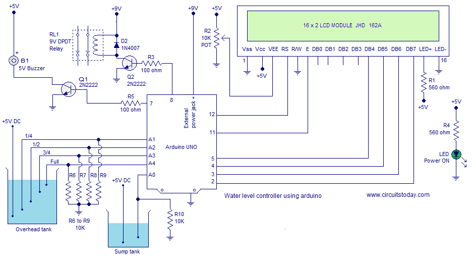
The circuit diagram of the water level controller using Arduino is shown above. Conductive method is used to measure the level. The sensor assembly consists of four aluminum wires arranged at 1/4, 1/2, 3/4 and full levels in the tank. The dry ends of these wires are connected to analog input pins A1, A2, A3 and A4 of the Arduino respectively. A fifth wire is positioned at the bottom of the tank. Resistors R6 to R9 are pull down resistors.The dry end of this wire is connected to +5V DC. When the water touches a particular probe, electrical connection is established between that probe and the +5V probe because water has slight conductivity. As a result current flows through that probe and this current is converted into a proportional voltage by the pull down resistor. Arduino reads the voltage dropped across each pull down resistor for sensing the level of water in the tank. Same method is used for measuring the level of water in the sump tank.
Digital pin 7 of the Arduino controls the buzzer and digital pin 8 controls the motor. Transistor Q1 drives the buzzer and resistor R5 limits the base current of Q1. Transistor Q2 drives the relay. Resistor R3 limits the base current of Q2. D2 is a freewheeling diode. POT R2 is used to adjust the contrast of the LCD. resistor R1 limits the current through the back light LED. Resistor R4 limits the current through the power ON LED. Complete program for the water level controller using Arduino is given below.
Program.
#include <LiquidCrystal.h>
int sump=A0;
int qut=A1;
int hlf=A2;
int thf=A3;
int ful=A4;
int motor=8;
int buz=7;
int s;
int q;
int h;
int t;
int f;
int i;     //motor status flag
int v=100; //comparison variable(needs some adjustment)
int b=0;   //buzzer flag
int m=0;   //motor flag
int c=0;   //sump flag

LiquidCrystal lcd(12, 11, 5, 4, 3, 2);

void setup()
{

pinMode(qut,INPUT);
pinMode(hlf,INPUT);
pinMode(qut,INPUT);
pinMode(ful,INPUT);
pinMode(sump,INPUT);
pinMode(motor,OUTPUT);
pinMode(buz,OUTPUT);
lcd.begin(16, 2);
digitalWrite(buz,LOW);
}

void loop()
{

i=digitalRead(motor);
s=analogRead(sump);
q=analogRead(qut);
h=analogRead(hlf);
t=analogRead(thf);
f=analogRead(ful);
lcd.clear();

if(f>v && t>v && h>v && q>v )
{
lcd.setCursor(0,0);
lcd.print(char(219));
lcd.print(char(219));
lcd.print(char(219));
lcd.print(char(219));
lcd.setCursor(5,0);
lcd.print("FULL");
m=0;
b=0;
}
else
{
if(f<v && t>v && h>v && q>v)
{
lcd.setCursor(0,0);
lcd.print(char(219));
lcd.print(char(219));
lcd.print(char(219));
lcd.print("_");
lcd.setCursor(5,0);
lcd.print("3/4th");
b=0;
}
else
{
if(f<v && t<v && h>v && q>v)
{
lcd.setCursor(0,0);
lcd.print(char(219));
lcd.print(char(219));
lcd.print("_");
lcd.print("_");
lcd.setCursor(5,0);
lcd.print("HALF");
m=1;
b=0;
}
else
if(f<v && t<v && h<v && q>v)
{
lcd.setCursor(0,0);
lcd.print(char(219));
lcd.print("_");
lcd.print("_");
lcd.print("_");
lcd.setCursor(5,0);
lcd.print("1/4th");
b=0;
}
else
{
if(f<v && t<v && h<v && q<v)
{
lcd.setCursor(0,0);
lcd.print("_");
lcd.print("_");
lcd.print("_");
lcd.print("_");
lcd.setCursor(5,0);
lcd.print("LOW");
b=0;
}
else

{
digitalWrite(motor,LOW);
lcd.setCursor(0,0);
lcd.print("ERROR!");
b=1;
}
}}}
if(i==HIGH)
{
lcd.setCursor(0,1);
lcd.print("Motor ON");
}
else
{
lcd.setCursor(0,1);
lcd.print("Motor OFF");
}


if(s>v && m==1)
{
digitalWrite(motor,HIGH);
}
if(s<v)
{
digitalWrite(motor,LOW);
lcd.setCursor(11,0);
lcd.print("Low");
lcd.setCursor(11,1);
lcd.print("Sump");
c=1;
}
if(s>v)
{
c=0;
}

if(m==0)
{
digitalWrite(motor,LOW);
}

if(b==1 || c==1)
{
digitalWrite(buz,HIGH);
delay(500);
digitalWrite(buz,LOW);
}
else
{
digitalWrite(buz,LOW);
}
delay(100);
lcd.clear();
}
About the program.
The Arduino reads the sensor output through the analog input pins using analogRead function. For example q=analogRead(qut); converts the voltage (in the range 0 to 5V) at the “quarter” probe into a number (in the range 0 to 1023) and saves it into the variable “q”. This way the voltage at each prob is scanned to corresponding variables. The these variables are compared to a fixed number (100 here) for identifying the current condition. Actually 100 is the equivalent of 0.48 volts and if the voltage at a particular sensor is greater than this, it is considered as an electrical continuity and water is assumed to be touching the probe. The vale of the fixed number (comparison variable”v”) needs some adjustment because the resistivity of water changes from place to place and the gap between the sensor probes will be different in different tanks.
Notes.
- The circuit is powered through the 9V external power jack on the arduino board.
- 5V needed at different points in the circuit can be tapped from the 5V output on the arduino board.
- Use good quality aluminum wires for probe. Do not use copper wires.
42 Comments
pls list the items used in the diagram
what if you don’t want to include the LCD screen
Here what is char 219
Please explain it
And if possible pls explain whole LCD programma line by line
List the more applications of water level controller using arduino
Sir,
I request you to make some changes in the circuit & code as per my need:-
1) Use Atmega328 with necessary components instead of UNO kit.
2) Only ON level & OFF level needed (instead of 1/4,1/2,3/4,Full) Manual push button switch for ON/OFF of motor.
3) Dry run protection (When the motor switches ON and if there is no flow of water to the OHT in the prescribed time (time adjust via variable resistor)
4) Flow LED, Motor ON LED, Motor OFF LED, No water in Sump LED to be included.
5) Buzzer gets activated when there is no Flow, Reset switch to restart after priming of the pump
6) Hi/Lo Voltage cutoff and when the voltage becomes normal the system continues to function. Hi/Low/Normal LED indication.
Warm Regards
Sir,
Can you please add dry run protection (with adjustable timing because when Motor switches ON, water takes some time to reach output)to the circuit and accordingly change the code (ie. dry run is, when the motor is switched ON and if any airlock happens) Dry run cutoff with LED indicator and buzzer alarm. Also please add high/low voltage cutoff circuit with necessary code changes.
Is it possible to use ATMEGA328P with bootloader (without using UNO board) if so please send updated circuit with code for the all the above.
Please reply ASAP.
Thank you
Warm Regards
S.AHaleem
Chennai
There is no motor present on the circuit diagram. where will we put the motor???
Motor will be connected at the other end of Relay
On what basis is the value of the comparison variable chosen ?
hello admin please mention the pinouts of relay in this circuit.iam starter in electronics.
How to connect relay to motor?
can i connect 12vdc dpdt relay?
plz clear my doubt with pinouts.
plz sir it’s urgent.
Sir. Will to tell me how to switch on the motor using the Arduino uno and which motor i have to take.
i tried it many times the same circuit + code with adjusting variable v=100 but doesnt work 🙁
WHERE IS THE MOTOR?? WATER IS TAKEN FROM THE SUMP TO THE MAIN TANK OR IT IS FILLED BY DEFAULT ??
I need a video with the connection of this project. could you provide ?
HI.
Using conductive method for sensing the water level is a BAD option. Why i say that? Because over time the water would corrode the metallic area that stay immersed all the time in the water, so over time false sensing is what we face.
We can use the RADAR technology for it. It means we will generate a few high frequency pulses and transmits it towards the target whose distance is to be measured. Then we detect the bounced back waves and calculate the distance. And none the less whatever RAW data we receive, we can process that to switch things & display text on display’s.
So going with the ultrasonic sensor is the way. HC-SR04
If we use HC SR-04 though, what additional changes need to be incorporated in the code?
please which of the aluminium wire is referred here? they are aluminium oxide wire and alot, please do clear me on it. secondly, have this project been built and tested? what is the motor specs used when you designed the circuit?
Controller is resetting while water pumps on.I think it is due to Electro magnetic interference.How to resolve this need help.
Nice work. If I do not need LCD interface and middle two probes (1/2 and 3/4) in overhead tank what changes I will have to make in software? Pl reply.
In the circuit diagram, please what’s the value of R6-R9
Can this be used with ultrasonic sensor in both the tanks?
Nice job! Am working on this circuit now. Immediately it works, I will alert you guys.
Dear,
really, this ckt is very good.
circuit is working properly
thanks
This is a very good project.It is 100% working.but motor on when water decrease half level.I want motor on when 1/4 level.please help me sir….
When i tried to upload code to ardunio uno it shows that “Sketch uses 3,310 bytes (10%) of program storage space” and i cant upload it to arduino..what will i do plz help CT.
sir i want to know weather the sensor will measure the waste materials level i mean a garbage in the streets
yeah we can know the garbage level by using weighing sensor or IR sensor.
sir,
can you please explain how to interface 16*2 lcd module with arduino uno
what software you use to draw the circuit and do the simulation.. i am final year stdent want to do this projectt for my last project
water level low but motor is not on
The water level controller that was installed at my house broke down and I adapted this circuit for controlling the water level. I am not using the LCD, instead I am using LEDs for indicating the water levels.
I have two overhead tanks – one for solar heater and the overflow of the solar tank fills a large overhead tank. When the overhead tank is full, the pump shuts off.
I have used ATMEL8A board for making this system.
The apparatus works for a while say about 10 mins and then things go haywire. The analog readings of the water level are no longer useable – fluctuates badly and the pump switches on and off intermittently. When I reset the microcontroller (MC)- the system works ok for some more time.
The overhead tank is about 25 feet from the MC and the solar tank is about 35 feet from the MC.
Is there anything that I need to take care to make it more stable?
I use AVR-Studio for developing the code.
Thanks inadvance.
dear,
really, this ckt is very good ,i tried somany ckt from circuit today ,i found all r working perfactly,and hope this ckt als working ,not yet tried.
Ramesh
your description is fine but i have some query that which relay is suitable to drive 1hp self priming monoset pump and how connection can be made?
tell me its urgent….,
you can use the relay mentioned in the circuit to control a coil controlled isolator(CCI) used in AC circuits. The relay will control the coil side of the isolator and the contacts will take care about the AC load. it will look like a MCB with additional AB contacts for the Coil. route the Coil circuit through the 9 V relay contacts.
Is there any simpler way to connect the the water pump without endangering any component in the circuit?
Hi! I am new to the world of electronics and wish to make a similar circuit. Could u please help in suggesting a simple, cheapest, durable and an automated solution (with maximum safety) for prototyping the circuit below? Thank You !
I have two AC motors, one for storing water in underground tank and the other for filling up overhead tank.
I start storing water in the underground tank once it comes during designated timings on alternate days only and it takes 8-10 hrs for tank to fill completely.
Sometimes it even happens that pump for underground tank is left running (not knowingly) and the water supply from utility during the designated timings is over while filling up the tank. In this scenario, the motor uselessly runs, until someone physically see the the flow of water and then switches it off.
After I see that there is substantial amount of water present in the sump, then only i switch on the other motor to fill up overhead tank or it would burn down the motor. The tank fills up in 90mins, if it’s completely empty. In this scenario too, one has to be there in time to switch off the motor once it has filled up completely to prevent overflow.
For this circuit, I would like to know the level of water using 5 LED indicators (EMPTY, 1/4, 1/2, 3/4, FULL) for both of my tanks.
More importantly, a manual switch in the circuit would be its plus point. So that if the circuit is malfunctioning, I would be able to connect the motors directly to mains.
Both are 2 HP motors and operate in 220V AC
What is the use of another tank below the main tank shown in figure
@sanjeev – It is sump tank used to represent water source (say well or a pond). If the level in side the sump tank is low, the motor will not be switched ON and this protects the motor from dry running.
Sir,
What is the Maximum length of the sensor wire of the aluminium sensing rods from the over head tank, we can use for the inputs to the arduino .
can we use any other sensing arrangement for this circuit ?
we require PCB for Water level controller using arduino c