Description.
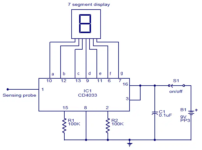
This circuit can be used to test whether mains voltage is present or not without having electric contact with mains line. The CMOS IC CD4033 is the heart of this circuit. The CD4033 consists of a 5 stage decade Johnson counter and an output decoder for converting the Johnson code to a 7 segment decoded output for driving 7 segment LED display. A 10cm long insulated copper wire connected to the clock pin (pin1) of the IC serves as the sensor. The sensor wire has to be placed in the vicinity of the mains wire to be tested. When there is no voltage in the mains line, no voltage will be induced in the sensor wire and the display will show a random digit. When there is voltage in the mains line, a small voltage will be induced in the sensor wire due to electromagnetic induction and this voltage is sufficient enough to clock the CMOS IC CD4033. Now the display will count from zero to nine and repeat.
Circuit diagram.
Notes.
- The circuit can be assembled on a Vero board.
- Use 9V PP3 battery for powering the circuit.
- Use a 10cm insulated wire as the sensor.
- The IC must be mounted on a holder.
- Switch S1 can be a miniature ON/OFF switch.


21 Comments
Is there any equivalent for IC CD4033 for this circuit ?? Coz i didn’t find any around my city . Plz answer thanks !
Try CD 4026
Plz perfactly explain the test of main supply any contact
this ckt is really works… thanx for the ckt…thats my mini project..
The mains voltage tester is a nice circuit to test the voltage. These type of Circuits are kind of foundation for the modern Testing Tools like Smart Tweezers.
what is the roll of resistors and capacitor in this wireless voltage tester?please suggest and reply
Thanks, it works, it’s beautiful! But more than count from 1 to 9 and to repeat, it seems that trembles, because the count is too fast. It looks more like a vibration that counts. If you can slow down this count, how to do? Thanks again, Toni Ipnos.
Wireless mains detector can also be built using 3 NPN transistors, 3 resistors & a 6v power supply. I have built this circuit and reviewed it. You can watch it at https://www.youtube.com/watch?v=RuNXPX-Mtxw&feature=youtube_gdata_player
please help me… i had made the same ckt about which u tell bt led continuously glowing… it does nt sense mains voltage..tell me what to do..?
use copper wire small…becoz it sense rapidly…
which type of probes should be installed???
Hai Readers,
The 7 segment display will blink continously.
So you can use this only for voltage indication purposes.
If you like you can try this
Wireless Mains Voltage Counter Circuit
this uses 3, 7 segment displays
Be Careful Folks when using this,,,,,,Safety Always FIRST!! Nice Circuit Never The Less!!!!
Hi Suyog you have to use common cathode display, cathode being connected to -ve common.
which 7 seg display(anode or cathode) should i use
hello sir, i purchased this equipment. I connected correctly but not working. It shows all segments are blinking but not induced any voltage when placed nearer to tested wire. Please tell me the solution sir.
Hi Chethan Babu.s 0.1 µf is ceramic disc type capacitor.9V PP3 Battry will work.You Must Use 7 Segment Common Cathode Type Display.Pin 3 or 8 connected to ground respictly.I made and it still work.Display fast count 1 to 9.You can see that all displays are blinking because they change at 50 Hz.
can ordinary 9v battery in not used here…? 9v pp3 is not yet available… tell me solution… i am waiting.. please reply fast
Wireless main voltage tester -I have purchased componenta and connected correctly but not working…, I doubt Ordinary 9V battery can use and wat typof capacitor is used 0.1uF —-? Volt..,