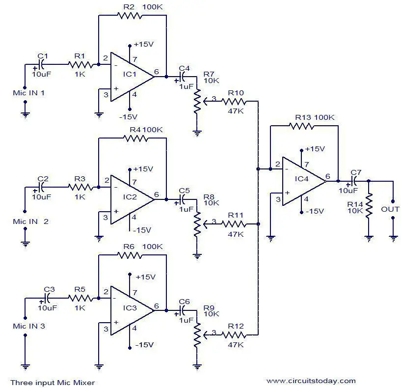
Description.
Here is a simple 3 input mic mixer circuit using the popular uA 741 ICs. Four 741s are used here.IC1, IC2, IC3 are used as preamplifiers. They produce a gain of around 40 decibel to the individual input signals. The IC4 is wired as a summing amplifier to add the signals from three preamplifiers.IC4 also gives a gain of around 5decibel to the final output signal. Total gain of the system is around 45decibel.
Circuit diagram with Parts list.

Notes.
- Assemble the circuit on a good quality PCB.
- A +15/-15 V DC dual power supply is needed for powering the circuit.
- All inputs and output must be connected with respect to the ground.
- ICs must be mounted on holders.
- Electrolytic capacitors C1, C2 and C3 must be rated 10V and other capacitors must be 30V.


I have made the scheme work.
The given scheme has a significant problem- the output sound level (voltage) is too high, and as a result, there is too much noise.
I have replaced R14 with a 7 kOhm trimmer (I did not have a 10 kOhm one), and I connected the audio output between the middle terminal of the trimmer and the ground terminal.
Then I adjusted it, until I got proper microphone level output signal. Now everything is fine.
I suppose that without modification the scheme could provide LINE OUT signal.
Sorry for the mistake, I meant “no sound comes out”, but I have written “sound comes out”.
I just assembled the scheme, but sound comes out.
I have connected no trimmers (R7), but I have connected C4 to R10 directly and the common terminal of both I have connected to ground. Could this be the reason of the failure?
I have checked my scheme and I found no mistake.
All my capacitors are 50 V.
Could I switch out two of the mic inputs for lets say a function generator and a synthesizer?
This is a good question, I don’t know the answer but if anyone knows the answer feel free to let us know! thanks
Please circuitstoday, what is the transfer function of this entire circuit?
Simulating this project on OrCad at the minute to make it as part of a college project, but the voltage readings around all the ICs are only in mili and micro volts, no matter what kind of an input is used with the signal generator. Should this be what I’m expecting with this particular circuit?
Getting pretty frustrated with it at the minute lol. Any help would be much appreciated.
how about a circuit that takes 2 unbalanced lines with 1 knob to balance between both? for example a guitar line and stompbox both 1/4″ unbalanced going out one 1/4″ unbalanced.
passive mixer to guitar amp with only 1 input.
please help me out!
why the 1st three ic gives the gain of 40db and not less or more than that ?
And why did the 4th ic which is working as summing amplifier gives a gain of 5db??
can someone pls provide me with the Circuit Manuel or the colour code for the resistors in the power supply for the Sound craft LX7II 32 Mono Mixing console.
Hi Al-Jabar you can use LM324 with 741 or TL074 with TL071
PLZ ME TO MAKE WIRELESS CIRCUT TX AND RX
hello, seethaman.,
i wanted to make a 4 input mic mixer, is it possible if i would just use a quad op-amp, then the output ic is the 741? will it be ok? or i should use the 741, then, i’ll be using 5.
can u send me that schematic to my address emmizeb@gmail.com
Hi Emmi you can use the above amplifier with a small modofocation. increase R1, R3 and R5 to 47K. connect two preamplifiers to two inputs of the above mixer and mixer’s output to a single amplifier.
Hello seetharaman
i want to use two preamps for one amplifier
how can i do this please tell me
seetharaman
can i use two preamps for one amplifier
noise is coming from output how can i reduce this