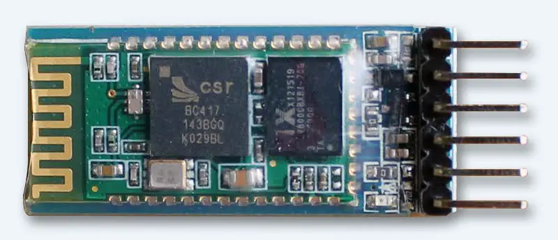
Bluetooth modules are used for short distance and point-to-point wireless data transmission and reception. The range of distance varies from module to module depending on the version of the module being used. For DIY projects, these are available as breadboard friendly modules. Even though these modules (hobby purpose modules) do not provide access to all those pins in the actual module (For Ex:- the GPIO pins ) provided by the manufacturer, these are fairly enough for wireless communication. In this article lets learn more about Bluetooth Module (HC 05 Bluetooth module) and how to interface a Bluetooth module to Personal/Desktop Computer (PC) via USB.
 The HC-03 and HC-05 modules are similar to each other, whereas the HC-04/HC-06 modules are different from the HC-05 module. The difference lies in the option to select the role of operation of the module. The HC-05 module can be operated in the Slave role as well as the Master role. The user can send appropriate commands to select the role of operation.

The role of operation of the HC-06 or the HC-04 module is preset by the manufacturer as factory settings. They operate either in the Master role or the Slave role. The User cannot select the role of operation for the HC-04/HC-06 modules after purchasing. The user should verify which operation mode the module is configured (master or slave) before purchasing.
Pin Configuration of the HC-05 Bluetooth module:
The Data transmission is based on the UART serial communication protocol through the UART pins of the module at 3.3 or 5 Volts TTL level. Typically, a blue tooth module contains the pins namely,
| S.No. | PIN Name | Description |
|---|---|---|
| 1. | +5V or 3.3V | +5V supply or Power Pin. |
| 2. | TX | The Data/Command to be transmitted is sent through this pin. |
| 3. | RX | The Received data is read from this pin. |
| 4. | KEY/EN | Input pin, which alters module between the Data mode and the AT Command mode. |
| 5. | STATE | Output pin, the state of the module is indicated through this pin. |
| 6. | GROUND | 0V / GND or Power Pin |
Working with the HC-05 Bluetooth Module:
Initially, to learn how to interface the UART Based modules, it is better to use a Hyper Terminal software. By connecting the Bluetooth module to USB-Serial converter, the data can be sent to the module and data received by the module can be read through the software. Many of the microcontroller Programming software’s contain the hyper terminal feature. Otherwise, there are third party hyper terminal Softwares.

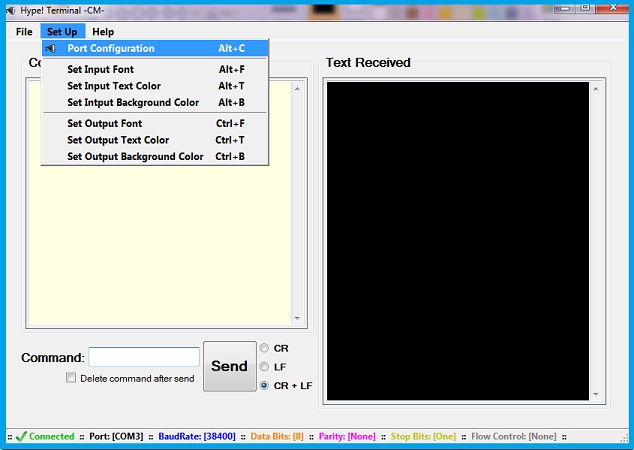
Using the Hyper Terminal Software:
In order to start communication with the module, the Serial Port should be configured. The Physical port number of the USB-Serial converter is obtained from the devices and printers under control panel. In the software, under set-up menu, select ‘port configuration’.
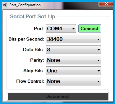
In the Port Configuration window, select the port of the USB-Serial converter, Baud rate of 38400, remaining parameters are generally the same by default. Click on the Connect button. After successful connection to the port, the status is displayed at the bottom of the software.
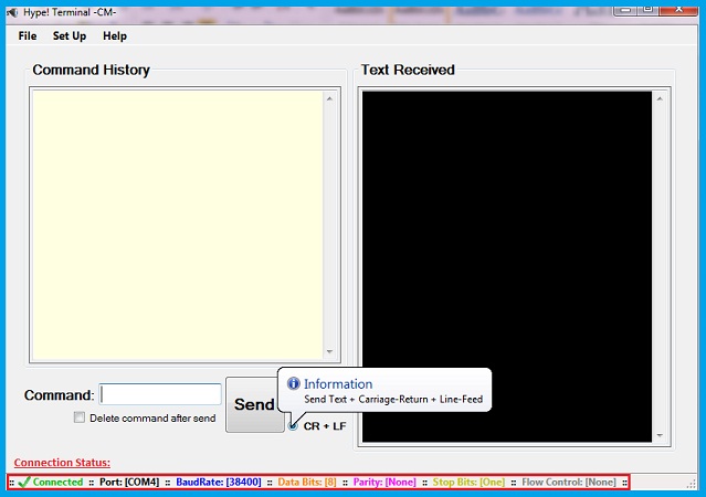
Every ‘AT’ command should end with \r\n. There is an option within the hyper terminal software to send Carriage Return ‘\r’ and Line Feed ‘\n’ characters as CR+LF. By enabling this option, these characters are sent after every command by default. The command to be sent is typed in the command box. By clicking on the Send button, the command is sent through the configured port.
AT Command Mode:
When the Key pin of the module is left open or connected to GND and the module is powered ON, the module operates according to the settings made during the previous usage. To know the role of operation or the name/address of the device and some other details, it is necessary to enter into the AT Command mode.
Most of the modules have a push button with the pin name of ‘EN’, in place of the KEY pin. Connect the Key/EN pin to +Vcc and power ON the module. Now, press the Key/EN switch. This will enter the module into the AT Command mode with 38400 Baud rate. This method is used to enter into the AT mode even if we do not know the previous settings. To send a command, it is required to press and hold the Key switch while sending the command. Otherwise, all the commands will not work.
To test the connection, send the command ‘AT’. ‘OK’ should be received under normal conditions. As mentioned earlier, every command ends with the characters CR and LF. These are not mentioned in the commands.
Name of the module:
The default name of the module is HC-05 in most cases. The module is visible to the other blue tooth devices with this name.
The name of the module can be inquired using the command,
| Command | Response |
| AT+NAME? | +NAME:HC-05
OK |
The name of the module can be changed using the command,
| Command | Response |
| AT+NAME=<Desired Name> | OK |
To verify the name, an inquiry should be done as in the previous case.

Address of the module:
Like the IP address for every system connected to the internet, every Bluetooth module has an address. This address is read by the remote modules for pairing. The name of the remote Bluetooth device can be fetched using its address.
The own address of the module can be inquired using the command,
| Command | Response |
| AT+ADDR? | +ADDR:1234:12:123456
OK |
The address of the Bluetooth device is shown in Hexa Decimal Format and it has three parts in the following format: NAP:UAP:LAP
NAP= Non-Significant Address Part (16-Bits)
UAP= Upper Address Part (8-Bits)
LAP= Lower Address Part (24-Bits)

Â
Passkey of the module:
The default passkey of the modules is ‘1234’. The command to inquire the passkey is,
| Command | Response |
| AT+PSWD? | +PSWD:1234
OK |
To set/change the passkey, the command is,
| Command | Response |
| AT+PSWD=<New passkey> | OK |
 Setting the Role of the module:
As mentioned earlier, HC-05 allows the user to make a selection of Role-Master/Slave. In either of the modes, wireless data transmission can be done. If the module say ‘A’, is set as a Master and a binding address of module say ‘B’ is specified, then after normal Power ON conditions, module ‘A’ builds connection with the module ‘B’, provided, the module ‘B’ is set to accept connection with any device.
The current role of the module is inquired using the command,
| Command | Response |
| AT+ROLE? | +ROLE:0
OK |
To set the role of the module, the following command is used,
| Command | Response |
| AT+ROLE=0 | OK |
0=Slave role
1= Master role
2= Slave-Loop (Data Received from the master is again sent to the master)
Address of the remote module:
In order to connect with remote devices, it is required to know the address of the remote devices. For this purpose, first set the module to master role and inquire the address of the remote devices in its range. The following series of commands are used,
| Command | Response |
| AT+ROLE=1 | OK |
| AT+INQ | +INQ:EC01:EE:B59A5C,5A020C,FFB9
OK |
It is of the format,
+INQ: Remote Device Address, Device Type, RSSI Signal intensity
 RSSI=Received Signal Strength Indicator
(The last two digits of this parameter vary with the distance between the module and the remote device. It is found practically by trial and error. Exact formulae are not known.)
This command shows the addresses of the available devices as a list. This list can be limited to the desired number of devices using the command,
AT+INQM=1,2,3
1=Class of device
2=Stop searching after 2 devices are identified
3=Search for 3*1.48 Sec

Name of the Remote module:
A master module can know the name of the remote device using its address, inquiry should be done using the command,
| Command | Response |
| AT+RNAME?Address of the remote device | +RNAME:HC-05
OK |
Using the Address Binding feature:
 To establish a connection with a particular module by default, its address can be fed to the master module, so that, master module always connects with that module. Binding can be done irrespective of the role of operation. This binding is done using the following command,
| Command | Response |
| AT+BIND=1234,56,123456 | OK |
To inquire whether the module is in bind with any other module, the following command is used to get the address of the module with which it is bind,
| Command | Response |
| AT+BIND? | +BIND:1234:56:123456
OK |
Connection mode of the module:
 Suppose we need to build a connection between two specific modules as a pair. Then, we can bind the address of the module to be paired in each module. To set the device for building connection with the module of predefined address, the following command is used,
| Command | Response |
| AT+CMODE=0 | OK |
Suppose there is a Bluetooth module which should be connected to any other remote device in its range, like the case, the module should be connected to a smartphone. Then setting should be done such that module can connect to any device, using the command,
| Command | Response |
| AT+CMODE=1 | OK |
There is another mode called the Slave-Loop mode similar to the Role 2. To inquire the current mode of the module, the following command is used,
| Command | Response |
| AT+CMODE? | +CMOD:0
OK |
These are the frequently used commands, which sufficient for establishing wireless data communication between two Bluetooth. Now, let us pair two modules and transmit data between them through the following example.
Hands-On Example-Pairing of two Bluetooth modules:
For this example, we need two Bluetooth modules, one USB-Serial Converter, USB Extension cord and accessories like connecting wires and breadboard.Â
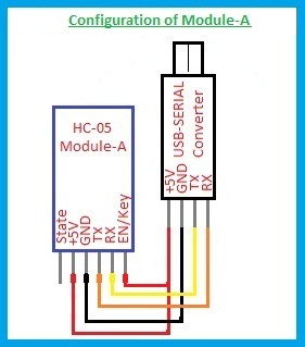
Step1: -Connect the Bluetooth module to the USB-Serial converter as shown. Run the hyper terminal software and configure the port.
Step2: -Configure the Bluetooth modules separately.
For this example, we have to configure one module say ‘A’ as Master and the other module ‘B’ as Slave.
Slave module configuration:
Supply Power to the module. Press and release the key switch to enter the AT command mode. In order to bind this module with master module, the address of this module is necessary. So, we have to inquire its address.
| Command | Response |
| AT+ORGL | OK |
This will set the module to default parameters.
CMODE=0
ROLE=0
PASS KEY=1234
So, the module is now set to operate in slave role and connect to the specified module.
By inquiring the address of the module, we can bind the address to the master module in the next step.
| Command | Response |
| AT+ADDR? | +ADDR:98d3:32:708b76
OK |
This is the received address for my module. Note the received address for your module.
| Command | Response |
| AT+CMODE=1 | OK |
Connect the module to any device.
Configuration of slave module
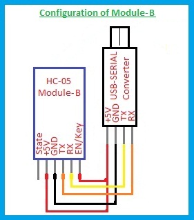
Master module configuration:
Now, place the second module exactly in place of the first module. Press and release the key switch to enter the AT command mode.
Set the module as Master,
| Command | Response |
| AT+ROLE=1 | OK |
As we already have the address of the slave module, let’s bind the slave module with the master module using the binding command.
| Command | Response |
| AT+BIND=98d3,32,708b76 | OK |
Now, we have fed the module with a specific address. This alone is not sufficient to allow the connection. Instruct the module to connect with the specified binding address.
| Command | Response |
| AT+CMODE=0 | OK |
Â
Configuration of Master module
Â
Step3: -Connect the modules with USB-Serial converter as shown below,
Â
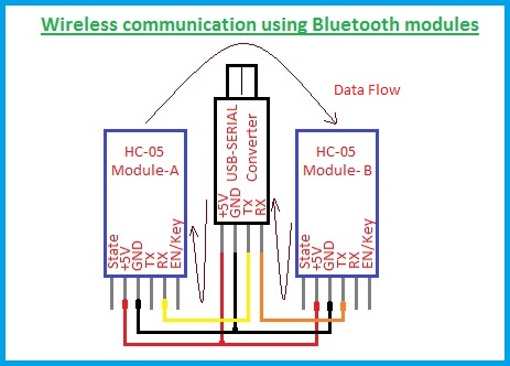
This connection is made in such a way that, we transmit the data from the master module to the slave module. From the hyper terminal software, we send the data to the master module and we receive the data from the slave module. Obviously, both the data are same i.e.., the text sent is received as it is. But the data is transmitted wirelessly from master module to slave module.
Wireless communication between configured modules
This is how, two Bluetooth modules can be connected for wireless communication. Suppose if there are two microcontrollers communicating through UART communication, to establish wireless transmission between them, these modules can be used with the above configuration. There is no necessity of KEY/EN pins. They can be left open after configuration.