H Bridge Motor Control
Given below is an H bridge motor control and  driver circuit using IC L298
Description :
A bidirectional H bridge DC motor control circuit is shown here. The circuit is based on the IC L298 from ST Microelectronics. L298 is a dual full bridge driver that has a wide operating voltage range and can handle load currents up to 3A. The IC also features low saturation voltage and over temperature protection.
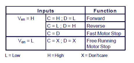
In the circuit diode D1 to D4 are protection diodes. Capacitor C2 is the logic power supply filter and capacitor C2 is the supply voltage filter. The state of the motor will depend on the logic level of the pins 10, 11, 12 and it is described in the table shown below the circuit diagram.
Circuit diagram of H bridge motor controller:

Â
Notes :
- Do not connect a motor that consumes more than 2.5A of current.
- The main power supply can be anything between 3 to 40V DC.
- It is advised to fit LM298 with a proper heat sink.
We have more articles of your interest related to H-Bridge:
1. H Bridge Motor Driver Circuit
Other Motor related circuits in our website:
3. Stepper Motor Driver Circuit
5. Low Voltage DC Motor Control Circuit
Â


Nice circuit ; simple ,clear explanation ,easy to build but i am in need of something more sturdy : Dc motor 24 V-,25 Amp (about 40 Amp just before stop).
So maybe instead of the BD 139 driver I gone to use a IGBT type: CH50DY-24H from Mitsubishi corp. & if needed bootstrap it with the Bd 139.
sincerely : Henk
Y should v give Vcc (3V to 46V) to D1 & D2?
The 4th pin would give the necessary supply na? Reply plzzz
Integrated Stepper Motor with Drives from UIROBOT Shanghai.