Half Adder and Full Adder Circuit
Half Adder and Full Adder circuits is explained with their truth tables in this article. Design of Full Adder using Half Adder circuit is also shown. Single-bit Full Adder circuit and Multi-bit addition using Full Adder is also shown.
Before going into this subject, it is very important to know about Boolean Logic and Logic Gates.
TAKE A LOOK : BOOLEAN LOGIC
TAKE A LOOK : LOGIC GATES
TAKE A LOOK : FLIP FLOPS
What is an Adder?
An adder is a kind of calculator that is used to add two binary numbers. When I say, calculator, I don’t mean one with buttons, this one is a circuit that can be integrated with many other circuits for a wide range of applications. There are two kinds of adders;
- Half adder
- Full adder
Half Adder
With the help of half adder, we can design circuits that are capable of performing simple addition with the help of logic gates.
Let us first take a look at the addition of single bits.
0+0 = 0
0+1 = 1
1+0 = 1
1+1 = 10
These are the least possible single-bit combinations. But the result for 1+1 is 10. Though this problem can be solved with the help of an EXOR Gate, if you do care about the output, the sum result must be re-written as a 2-bit output.
Thus the above equations can be written as
0+0 = 00
0+1 = 01
1+0 = 01
1+1 = 10
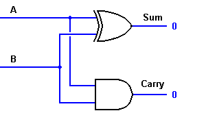
Here the output ‘1’of ‘10’ becomes the carry-out. The result is shown in a truth-table below. ‘SUM’ is the normal output and ‘CARRY’ is the carry-out.
INPUTS OUTPUTS
A B SUM CARRY
0 0 0 0
0 1 1 0
1 0 1 0
1 1 0 1
From the equation, it is clear that this 1-bit adder can be easily implemented with the help of EXOR Gate for the output ‘SUM’ and an AND Gate for the carry. Take a look at the implementation below.

For complex addition, there may be cases when you have to add two 8-bit bytes together. This can be done only with the help of full-adder logic.
Full Adder
This type of adder is a little more difficult to implement than a half-adder. The main difference between a half-adder and a full-adder is that the full-adder has three inputs and two outputs. The first two inputs are A and B and the third input is an input carry designated as CIN. When a full adder logic is designed we will be able to string eight of them together to create a byte-wide adder and cascade the carry bit from one adder to the next.
The output carry is designated as COUT and the normal output is designated as S. Take a look at the truth-table.
INPUTS OUTPUTS
A B CIN COUT S
0 0 0 0 0
0 0 1 0 1
0 1 0 0 1
0 1 1 1 0
1 0 0 0 1
1 0 1 1 0
1 1 0 1 0
1 1 1 1 1
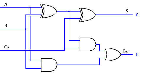
From the above truth-table, the full adder logic can be implemented. We can see that the output S is an EXOR between the input A and the half-adder SUM output with B and CIN inputs. We must also note that the COUT will only be true if any of the two inputs out of the three are HIGH.
Thus, we can implement a full adder circuit with the help of two half adder circuits. The first will half adder will be used to add A and B to produce a partial Sum. The second half adder logic can be used to add CIN to the Sum produced by the first half adder to get the final S output. If any of the half adder logic produces a carry, there will be an output carry. Thus, COUT will be an OR function of the half-adder Carry outputs. Take a look at the implementation of the full adder circuit shown below.

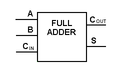
Though the implementation of larger logic diagrams is possible with the above full adder logic a simpler symbol is mostly used to represent the operation. Given below is a simpler schematic representation of a one-bit full adder.

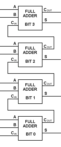
With this type of symbol, we can add two bits together taking a carry from the next lower order of magnitude, and sending a carry to the next higher order of magnitude. In a computer, for a multi-bit operation, each bit must be represented by a full adder and must be added simultaneously. Thus, to add two 8-bit numbers, you will need 8 full adders which can be formed by cascading two of the 4-bit blocks. The addition of two 4-bit numbers is shown below.


42 Comments
how make The output carry and the normal output as S in one output in full
adder
ooohh, thanks sir, youve help me overcome my anxiety with this information. Now I can successfully deal with my wifes avrotion without having to use a coat hanger
so nice explanation it can be understood easily….
Nice information
Sir how to make a 4 bit full adder using half adder
This was a great explanation. Loved it thank you very much
Sir, wouldn’t it make more sense to use a half adder for the 0-bit, it would reduce the number of transistors by almost 1% in a 64 bit system and nearly 5% in a 32 bit system. or is there something I’m not seeing.
what the number of the new ic design full adder by 2 half adder ?
thank u shaktiman
cool notes here. simple and exact.
honestly I had a problem with these adders so you played a prominent role in my life….thank you may God bless you
its Realy Nice Sir
Thnx a lot 🙂
sir is there a way to establish a full adder with only 3 gates not 5 ?
sir i want a 2-bit half adder and full adder table….
you did not clearly explain the difference between half and full adder.its not sufficient method for bignners or students to understand it.
please give the logic diagram of full adder using NAND,NOR GATES
The demonstration is Crystal clear!
How to make full adder circuit using two half adder circuit
very useful for physics hons. student…..too simple too understand.:-)
Nice Sir,very simple and clear explanation
NOT FULFILLED WITH THE RESULT
Awesome n easy explanation. thanks sir for such a great work
Fantastic ideas…
Thanks sir for simple and clear explanation
sir,i have to know the brief explanation of truth table of full adder
sir please specify the important question list from ‘combination&sequential logic circuits’
sir i need your help. and be-3 sem ADE sub in MOST IMP quns. for GTU.
sir,please specify the applications of full and half adders in brief manner.
Hi Mounika say you have four full adders you can make a 4 digit display that is from 0 to 9999. if you take the first overflow and set as 1 before 9999 it will become 19999, the measuring range is doubled with simple one overflow counter from 9999 to 19999. with second overfow it will indicate over range. Due to this half adder additon say to a 3 digit meter with a measuring range of 0-999 is increased 0 to 1999. That is why the 999 meter is called a 3 digit meter and 1999 is called 3 1/2 digit multimeter (as the half adder is added to double the measuring range).
Thank u very much the article is a very 9c 1
sir,i need ur help i want to know about on application of full and half adder and its working. Thank you
its awesome article…. its very useful… but it may have little simplification
its very useful for me…
hi!i wnt to know hw to design a circuit?
@priya – What kind of circuit ? Please specify!
sir i need your help. i want the information about half adder and full adder using operational amplifier.
thanks
sir,i need ur help,i want to know about on applications of full and half adder using logic gates,please response as soon as possible, thank you
Hi newbie in https://www.circuitstoday.com boards.
great to become member of this neighborhood
PS Mod: Please take away this thread if it isn’t the appropriate place this category:
__________________________
[url=http://32incheslcdtv.info/]32 inches lcd tv[/url]
respected sir ,
i wants your help , i wants to know about on application of different type of capacitor in deep .
i have a also one more request sir ,
i wants to know about IR led and how does they work and why do we use IR led in remote operation and etc.
sir please show your response immediatly as soon as possible , i will very thankful your for this.
pls email me with this topic
“HAVE A NICE DAY”
Thanks a lot sir for your helpful information
Very clear and understandable