In this article, we are going to interface the GY-521Â accelerometer with Arduino. The GY-521 has an InvenSense MPU6050 chip which contains a 3-axis accelerometer and a 3-axis gyro meter. This makes it a 6 DOF IMU (6 degrees of freedom inertial measurement unit). The chip also includes a 16-bit analog to digital converter on each channel and a DMP (Digital Motion Processor) unit. The DMP unit is responsible for combining the raw data and performing some calculations to remove the errors in each sensor.
Pin Out Diagram – GY-521
The GY-521 breakout board has a total of 8 pins which are as follows:
VCC: 5V or 3.3V pin
GND: Ground pin
SCL (Serial clock line): Responsible for the primary I2C communication
SDA (Serial data line): Responsible for the primary I2C communication
XCA (Auxiliary clock line): Responsible for the Auxiliary I2C communication
XDL (Auxiliary data line): Responsible for the Auxiliary I2C communication
ADO:Â Responsible for slave or master interface
INT: Interrupt Pin
The breakout board has a voltage regulator for converting the voltage level from 5V to 3.3V and also has an InvenSense MPU6050 chip which holds the accelerometer and gyro meter sensors.

Specifications
The specifications of the GY-521 MPU6050 are as follows
- The accelerometer sensor range is ±2, ±4, ±8, ±16g
- The gyro meter sensor range is ±250, ±500, ±1000, ±2000 ͦ/s
- The voltage range is from 3.3V to 5V. We can give 5V input because the sensor module has a voltage regulator for converting the 5V input into 3.3V
Working
The accelerometer sensors measure the acceleration by measuring the change in capacitance. Its structure has a mass attached to a spring which moves along one direction and has fixed outer plates. So, when acceleration is applied in any direction, the capacitance between the plates and the mass will change. This change in capacitance is measured and corresponds to the acceleration value.
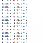
The Arduino reads these acceleration values from the sensor and then calculate the pitch and roll values using the functions provided by the MPU6050 library. These pitch and roll values are shown on the serial monitor output screenshot given below. Whenever we move the sensor, the pitch and roll values on the serial monitor will change according to the movement.
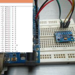
Circuit Diagram
Connections of the GY-521 MPU6050 with the Arduino Uno are as follows
- VCC of GY-521 to 5V or 3.3V of Arduino Uno
- GND of GY-521 to GND of Arduino Uno
- SCL of GY-521 to A5 of Arduino Uno
- SDA of GY-521 to A4 of Arduino Uno
The SDA and SCL pins of the GY-521 are used for I2C communication, so these pins must be connected to the SDA and SCL pins of Arduino. The SCL and SDA pins on Arduino Uno are the A5 and A4 pins (look at analog pins) respectively. Therefore, we connect the SDA and SCL pins of GY-521 to A5 and A4 pins of Arduino Uno.
The GY-521 MPU 6050 also has two auxiliary SDA, SCL pins, which are an additional I2C controller for the GY-521 MPU6050. These additional pins allow GY-521 MPU6050 to act as a master for the second I2C bus. The purpose of this additional I2C is that if you want to add another sensor (for ex: magnetometer), then you can directly attach it to the GY-521 which will then read the values.

Code/Program
Before uploading the code in the Arduino IDE, Download the library from here and add it into the library folder.
#include <Wire.h>Â Â Â Â // Including the wire library
#include <MPU6050.h>Â // Including the MPU6050 library
MPU6050 accelerometer;Â Â Â Â Â Â Â Â Â // Initializing a variable name accelerometer of type MPU6050
void setup()
{
Serial.begin(115200);Â Â Â Â Â Â // Starting the serial communication at 115200 baud rate.
Serial.println("Initializing the MPU6050 sensor. Wait for a while");
delay(2000);
while(!accelerometer.begin(MPU6050_SCALE_2000DPS, MPU6050_RANGE_2G)) // Checking whether the mpu6050 is sensing or not
{
Serial.println("Failed to read from the sensor. Something is Wrong!");
delay(500);
}
}
void loop()
{
Vector sensor_data = accelerometer.readNormalizeAccel();Â Â Â // Reading the acceleration values from the sensor
int pitch_value = -(atan2(sensor_data.XAxis, sqrt(sensor_data.YAxis*sensor_data.YAxis + sensor_data.ZAxis*sensor_data.ZAxis))*180.0)/M_PI;Â // Calculating the pitch value
Serial.print(" Pitch = ");
Serial.print(pitch_value);Â Â Â Â Â Â Â // Printing the pitch values on the Serial Monitor
int roll_value = (atan2(sensor_data.YAxis, sensor_data.ZAxis)*180.0)/M_PI;Â Â Â // Calculating the Raw value
Serial.print(" Roll = ");
Serial.println(roll_value);Â Â Â Â Â Â Â // printing the Roll values on the serial monitor
delay(10);
}
Code Explanation
First of all, we need to include the libraries. The wire library allows the I2C communication between the Arduino and the sensor. The GY-521 MPU6050 sensor communicates with the Arduino through I2C protocol, so we need to add the wire library. The MPU6050 library helps us to read from the sensor and get the pitch and roll values. Â Finally, Â we declare a variable named accelerometer of type MPU6050.
#include <Wire.h>

#include <MPU6050.h>

MPU6050 accelerometer;
In the setup function, we checked whether the accelerometer is sensing properly returning us the values or not. If the sensor is functioning proper, then Arduino will receive the values to calculate the pitch and roll values. Otherwise, the Arduino will print “Failed to read from the sensor. Something is Wrong!“)†on the serial monitor.
while(!accelerometer.begin(MPU6050_SCALE_2000DPS, MPU6050_RANGE_2G))

{

Serial.println("Failed to read from the sensor. Something is Wrong!");

delay(500);
After that, we take the readings from the MPU6050 sensor and store in a variable named ‘sensor_data’. Then we calculate the pitch values using the read sensor data values and show these values on the serial monitor.
Vector sensor_data = accelerometer.readNormalizeAccel();
int pitch_value = -(atan2(sensor_data.XAxis, sqrt(sensor_data.YAxis*sensor_data.YAxis + Â Â Â Â Â Â Â Â Â Â Â Â Â Â Â Â Â Â Â Â Â Â Â Â Â Â Â Â Â Â Â Â Â Â Â Â Â Â Â Â sensor_data.ZAxis*sensor_data.ZAxis))*180.0)/M_PI;
Serial.print(" Pitch = ");
Serial.print(pitch_value);
Similarly, we calculate the roll values using the sensor data  and show these values on the serial monitor.
int roll_value = (atan2(sensor_data.YAxis, sensor_data.ZAxis)*180.0)/M_PI;

Serial.print(" Roll = ");

Serial.println(roll_value);

delay(10);
So here we finish the tutorial on how to interface an Accelerometer to Arduino. If you have doubts, please ask in comments.
Output Screenshots!
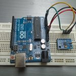
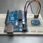
Photographs

i have a doubt that is how to display the values that is change in acceleration. in lcd display fromm arduino and how connect arduino witj lcd display and whether it require any coding