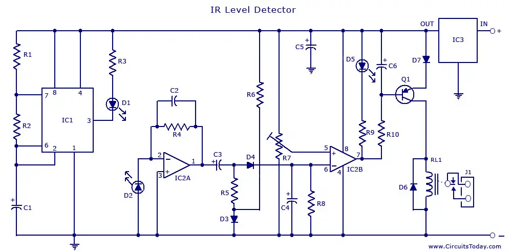
InfraRed (IR) Sensor/Detector Circuit
The IR circuit described below is mainly designed for liquid level detection or proximity detection. The IR sensors used here are an IR LED and an IR photo diode. The circuit operates by detecting the distance from the target by reflection of an infrared beam. The biggest advantage of this circuit is that there is no physical contact with the liquid whose level is to be measured. Such a circuit needs to be installed only once, and can be used for years, as there is no corrosive elements.
You may also like: Simple Water Level Indicator
The circuit shows that the output of IC1 555 IC, which is designed for a duty cycle of 0.8mSec, with a frequency of 120Hz and 300mA peak current, is used to drive the infrared LED, D1. From the connection it is clear that the diodes D1 and D2 are on the same line, just a few centimeters apart, on the breadboard. Thus diode D2 receives the infra-red output from the diode D1. The diode signal, which is given to the inverting terminal of the op-amp IC LM 358 gets amplified and its peak is detected by diode D4 and capacitor C4. The forward voltage produced by diode D4 is compensated by diode D3 with R5 and R6. According to the distance between the infrared transmitter and receiver, a proportional DC voltage is fed to the inverting input of IC2. According to the output of the comparator the LED is turned ON and OFF and this is detected by the transistor Q1. Thus the relay is driven according to the output of Q1. The comparator output is set according to the value of the pot.
You may also like: DIY Infrared Motion Detector Circuit
The range is set by adjusting the pot. Range can vary, depending on infra-red transmitting and receiving LEDs used and is mostly affected by the color of the reflecting surface. Black surfaces lower greatly the device’s sensitivity.
You may also like: PIR Sensor Based Security System
NotesÂ
Use a good quality regulated power supply. The sensor diodes must not be subjected directly to other light sources.
Parts ListÂ
| Component | Specification |
|---|---|
| Resistance R1 | 10K(4W) |
| Resistance R2, R5, R6, R9 | 1K(4W) |
| Resistance R3 | 33K(4W) |
| Resistance R4, R8 | 1M(4W) |
| Trimmer Cermet R7 | 10K |
| Resistance R10 | 22K(4W) |
| Capacitance C1,C4 | 1 uF(63V) |
| Capacitance C2 | 47pF(63V) |
| Capacitance C3, C5, C6 | 100uF(25V) |
| Diode D1 | IR LED |
| Diode D2 | IR Photo-Diode |
| Diode D3, D4 | 1N4148(75W/150mA) |
| Diode D5 | LED |
| Diode D6 ,D7 | 1N 4002 |
| PNP Transistor Q1 | BC 558(45V/800mA) |
| Timer IC IC1 | NE555 |
| IC2 | LM358 |
| IC3 | 7812 |
| Relay | SPDT(2A/220V) |
| J1 | Two ways output socket |


sir actually i want to know how to calculate time which an object takes between two IR sensors having a known distance.so what timer or IC i should use in my project.how to inerface that IC with IR.I want to use this for calculating a speed of a car on the road.
please any new ideas mail me……………..
Hi guys..
I tried this circuit but it seems that this is not working..
I can only managed to on/off the LED indicator by the trimmer resistor other than that there was no output in my RL1.For my understanding there should be a differential voltage in the RL1 once the IR was deactivated right?Because D1 is always on.
Need you input guys.
I really need this project to work.
Thanks!
THERE IS A LOT OF KNOWLEDGE IN INTERESTING WAY.THAT IS VERY HELPFUL FOR ME. SO SPEACIAL THANX OR YOU.
Best you should make changes to the blog subject IR Level Detector to more specific for your content you write. I enjoyed the blog post nevertheless.
i made the circuit,the connections are all right but the problem is that LED is not working properly.either it remains off or on,even my amplifier part is correct.please give any suggestion.
There is obviously a lot to know about this. I think you made some good points in Features also. Keep working ,great job!
Thanks again for this very interesting circuit!!
May I know exactly the wattage of the resistors, were they of 4 watts, or 1/4 watt?
My other question is ; what is the required voltage for the coil of the relay?,,
and what is the ideal distance between the IR LED AND PHOTODIODE to be installed from the top of a 3 meter high water tank? Can I wire the IR LED and IR PHOTODIODE from the top of the tank going to the circuit board away from the tank to safeguard the board from moisture accumulation?
can the moisture that accumulates on the sensors inside the tank when the weather is hot affects the sensing characteristic?
what would be the other equivalent transistor for the Q1 if it is not available?
Looking forward for the reply the soonest.
More power to you.
Edgardo
Yes, can you post a digital display circuit to know the liquid level inside tha tank.Good circuit!!! more power to you!!!
hi I cannot find an ir photodiode. I found one which has three pin connection. your circuit shows 2 pin connection. how can i use the three pin connection.
thanks.
good circuit !!
what of if you want to include a digital display circuit to indicate levels of liquid as it moves towards or further from the sensor