Description.
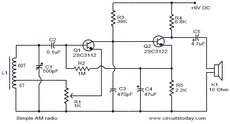
This is a very simple AM radio circuit using only two transistors. The coil L1 and variable capacitor C1 forms the tank circuit. Transistor Q1 does the job of demodulation. The demodulated signal will be available at the base of Q1.This audio signal is coupled to the base of Q2 for further amplification. The amplified audio signal will be available at the collector of Q2. Please note that, this circuit will work properly only in places with good signal strength.
Circuit diagram.
Notes.
- The circuit can be assembled on a Vero board.
- A 9V PP3 battery can be used for powering the circuit.
- Coil L1 can be made by making 65 turns of 24SWG enameled copper wire on a 100mm long, 10mm diameter ferrite rod. A tapping must be made on the fifth turn.


use a red match tranformer for audio circuits
use audio transformer to match output for better sound using an 8 ohm speaker.
What is 24SWG
24 no standard wire guage
Hi Lateef you can try the following ones.
http://www.zen22142.zen.co.uk/Circuits/rf/fmreceiver.htm
http://www.somerset.net/arm/radio_pictures/radio_shack_28-115_sch.jpg
I need a circuit diagram of an FM RADIO RECIEVER with details