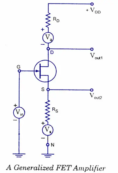
FET Amplifier
The circuit consists of three independent signal sources (Vin in series with the gate, VS in series with the source, and VA in series with the drain). For common source amplifier V0 = Vs = 0, and the output Vout 1 is taken at the drain terminal D, as shown. For common gate circuit Vin = VQ = 0, the input signal is VS with a source resistance RG, and the output Vout 1 is again taken at the drain terminal D. For the common drain (or source follower) RD = 0, VS = VA = 0, the input signal voltage is Vin and the Output Vout 2 is taken at the source terminal. The signal-source resistance is ineffective as it is in series with the gate which draws almost no current.
Thevenin’s equivalent circuit from drain to ground and from source to ground is given in the figures below.

From the circuit named “looking into the drain” of the FET it is seen (for small signal operation) an equivalent circuit consisting of two generators in series, one of – u times the gate signal voltage Vin and the second (u + 1) times the source-signal voltage Vs and the resistance rd + ((a + 1) RG. Note that the source-signal voltage Vs and the resistance in the source lead are both multiplied by the same factor, (u + 1).
1 Comment
can u send me a inverter circuit diagram without using transformer for a rating of 12v-220v ac for 100watts?