Robotic Arm Project Using Arduino
Nowadays, manual labor is being reduced at big scale industries and factories to increase efficiency and gain profit by installing robots that can do repetitive works. A onetime installation of such a device may cost a huge amount, but in the long run, will turn out to be more profitable that manual labor. Out of the lot, a simple robotic arm is one of the most commonly installed machines. We are introducing the basic concepts of an Arduino controlled robotic arm project.
The programmable robotic arm finds extensive applications in its use in extreme conditions like space mission or underwater expeditions. It is also using in nuclear power plants and in toxic atmosphere
where human surveillance is difficult.
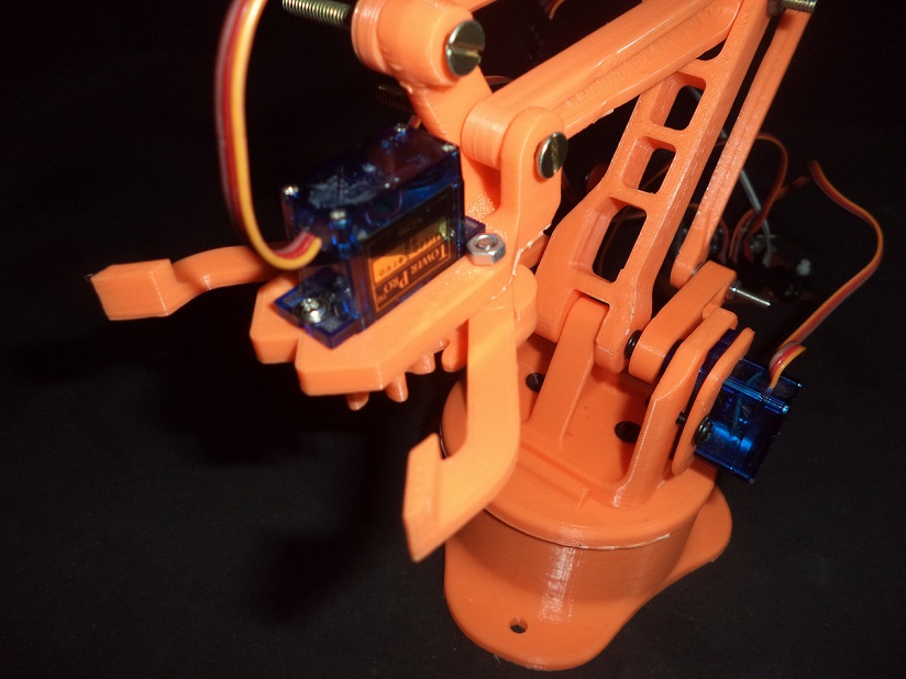
There are numerous types of robotic arm used in industries but going to give you details on a basic prototype. The movement of parts is done by servomotor, which can rotate approximately up to 190 degrees. The whole circuit is powered by 12-volt adapter and an Arduino Nano is used as the controlling unit. The servo motor for robotic arm is controlled by android mobile. The communication between mobile phone and servo robot arm is done by Bluetooth module HC-05.
Components Used
| Components | Specifications | Quantity |
|---|---|---|
| Arduino | Nano | 1 |
| Servo Motor | G9 | 4 |
| Robotic Arm | 3D Printer Parts | |
| Bluetooth Module | C-05 | 1 |
| Power Adaptor | 12 Volt | 1 |
Arduino Robotic Arm Project – Working
The mini-robot arm uses four servomotors to move the arm. Servomotors are controlled by Arduino and connected to the PWM pin of Arduino. There are eight buttons in the android app. Out of these, four buttons are used to control the four servo motors. One button is used for clockwise rotation and other is used for anticlockwise of the mini robot arm.
The Bluetooth app interface is shown in the figure below.
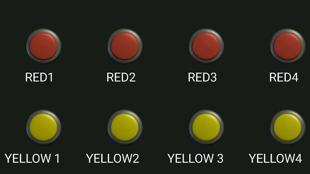
Out of eight buttons, four buttons are Red and four are Yellow. When a button is pressed it sends a unique character to Arduino via Bluetooth. As soon as the Arduino receives the character, its command is identified and rotates the servo motor accordingly.
For clockwise rotation of servo motor the red button in the application is to be pressed. Four buttons are used for each servomotor. When the red button is pressed it sends two types of characters. First is the press character and the second is the release character. When a button is pressed, a character is sent through Bluetooth and the Arduino rotates the servo motor one degree in one cycle. If button is not released servomotor moves one degree in next cycle.
This same process is also used when yellow buttons are pressed, but this time the servo motor rotates one degree in the anticlockwise direction. Press and release characters are shown in the table given below.
Programmable Robot Arm – Press and Release Characters
| Switch | Press Char | Release Char |
|---|---|---|
| RED1 | A | a |
| RED2 | B | b |
| RED3 | C | c |
| RED4 | D | d |
| YELLOW1 | Z | z |
| YELLOW2 | Y | y |
| YELLOW3 | X | x |
| YELLOW4 | W | w |
Arduino Robotic Arm Project – Circuit
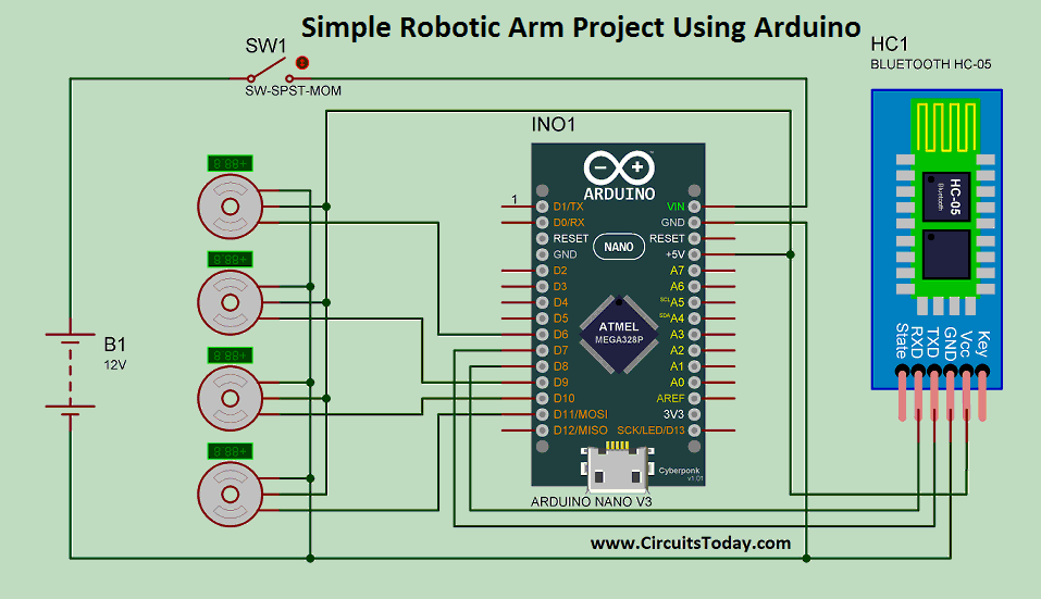
In the circuit, Arduino Nano is used and Bluetooth module HC-05 is connected to it. Servomotors are connected to PWM pins
of Arduino and the circuit is powered with 12 volt DC adapter.
There are three pins in the servo motor. One is the Vcc, other is the GND, and the third is the SIG pin. The SIG pin is connected to PWM pins of Arduino. The pins 6, 9, 10 and 11 are connected to the servomotor. Bluetooth module has four connecting pins. Two of them are Vcc and GND. The other two are Rx and Tx pins. Rx pin is connected to pin 8 of Arduino and TX pin is connected to pin 12 of Arduino.
In the robotic arm project using Arduino, an etched PCB is used. The PCB design is given below.
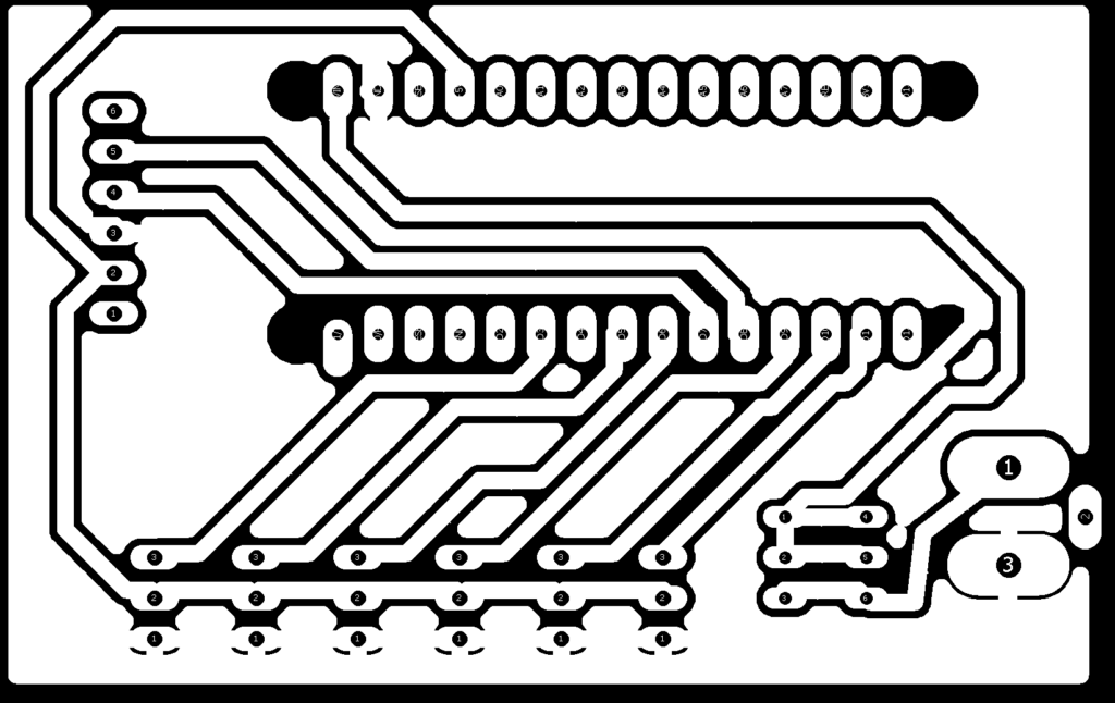
The circuit diagram is given below.
Assembly of 3-D Printed Parts
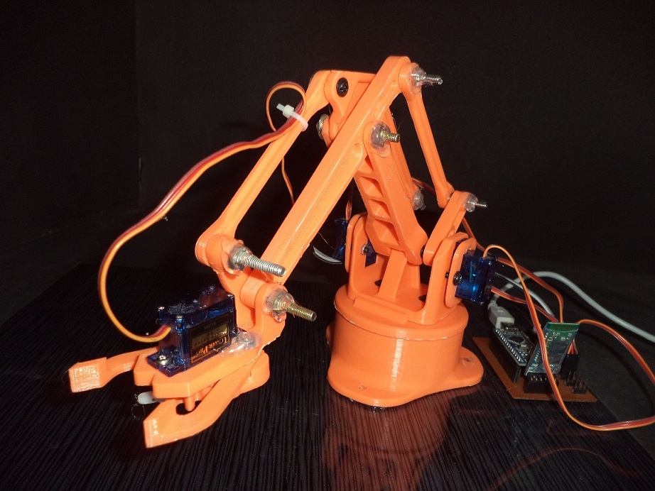
3d printed parts are used in the arm. Please visit the link http://www.instructables.com/id/EEZYbotARM/ for assembly of parts. If you have 3d printer you can download the files from the link or visit any e-commerce site (eBay/ Amazon).
Simple Robotic Arm Project – Video
Customization of App
Customization of app is shown in the video below.
- Download the app “Bluetooth Electronics” from Playstore.
- Open the app and touch on empty space.
- In the right side touch on buttons, now buttons are visible in bottom.
- Drag and drop the buttons as shown in video.
- Select any button and assign the “press char” and “release char” as shown in fig1 and Table2.
- Repeat these steps for every button.
Program/Code
In the beginning of code, two header files are used. The first one is “SoftwareSerial.h” which is used for Bluetooth module and the second is “servo.h” which is used for servo robot arm. Now Bluetooth Rx and Tx pins are defined by function “Software Serial mySerial (7, 8)” in which pin 7 is connected to Rx pin of Bluetooth module and pin8 is connected to Tx pin.
Now servomotors are declared by function “Servo myServo”. Four servos are declared by the same function from line 6 to 9. After that, four integers are declared by names pos1 to pos4. All integers are equal to 90 (degree), which is the starting position of servo motor. Another integer is declared by name “in” which is equal to input char coming from mobile phone.
In the void setup “mySerial.begin(9600)” is used for beginning of
communication using Bluetooth. All the servo motors are activated using “myServo.attach()”
In the void loop, mySerial.available() is used in if loop, it will execute
when data receiving from mobile side. Now this char is assigned in the
intiger “in”.
In the line “32 in == ‘A’ “is used inside the “if†loop when it become true pos1 starts increasing. Same condition is used in line 33 for Z it decrease the value of pos1. These conditions are used for pos2, pos3 and pos4. Now “myServo.write(pos)” function is used for moving at the “pos” position.


Comments are closed.