Description.
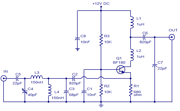
The circuit shown here is of a TV antenna booster based on the transistor BF180. The circuit operates in the UHF band and has a gain of 15dB. Capacitors C2,C3 C4 ,C5 and inductors L3, L4 forms a UHF band pass filter. The input signal is fed to the emitter of Q1 through this filter. Resistor R2 and R3 biases the transistor Q1 which is wired in the common base configuration.
Circuit diagram.
Notes.
- Assemble the circuit on a good quality PCB.
- For better performance, enclose the circuit in a metal box.
- The circuit can be powered from 12V DC.


26 Comments
How to check circuit with DMM if it’s working? Thanks.
Seetharaman jee, can I use this circuit as add-on to my UHF tv transmitter circuit in between the circuit and the antenna? Thanks
sir can i use BC547 to replace the transistor. tanx for the ckt
where will i feed my cathode (-) from 12vdc to my circuit board
Negative to common shown as ground.
Pls i want to know what is wrong wit my antenna the signal strength is very low
Check for corrosion in the connecting leads, Dipole edge connections at the clamp end. directors and reflector also should be clean at the clamp end. The dipole should not touch each other at the wire connecting end. You check the continuity of the antenna wire at the receiver end it should be 15 to 50 ohms depends on the length of the cable used from antenna. Do not coil the excess length of the cable anywhere. cut the excess length use only the required length of cable. Check also the direction of the antenna
tv antenna amplifyer circuit
Pls send right up on fire alarm using thermistor
please wht is the function of L1 and L2 and C7, C6, C8, C1, R1. I have to defend this in my project please.
did u have answer to it and did the circuit work wen u use it for ur project
saya membutuhkan antena yng cocok untuk di daerah pegunungan yng sinyalnya sangat lemah sekali. tolong ksik petujuk/ jawabannya. thankyou
Could you please send me a PCB layout of this TV booster circuit. Thank you very much.
thanks alot. Ill makd one
In winding inductors for RF designs, this measuring circuit allows the designer to know exactly when the desired inductance has been achieved. As an example, the number of turns for a single layer air core inductor is given by
N =[ √l X (9a + 10b) ]/ a²
where
l = inductance in microhenries,
a = coil radius in inches,
b = coil length in inches,
N = number of turns.
How do you know what guage wire to use with this formula?
Hi whow can i make those inducters as they are not aveilable in market?
woo. It works well but how can i increase gain?
Hi use cable TV amplifier appeared earlier on this site
Hi
for VHF?
PLEASE HELP ME
Hi Howard use a low pass filter for DC and Hi Pass filter for the RF. (just a capacitor to block DC and a choke to block RF.
I’d like to build manhatten-style (point-point, directly on a copper-clad board), mount it on the back of a UHF bow-tie antenna, and powered from a wall-wart at ground level. How can I separate the DC power from the RF if I use only the RG-6 feeder cable for the interface?
Hi Manir you can use 2N918 BF594 BF597 BF595 BF197 BF195 BF194 BF195 BF 173 BF176 any high frequency transistor can be tried
Hi,
BF180 is not available in the stores around Toronto, 2SC2570 is not either.
What are the substitutes of BF180?
Thanks.
Manir
Hi Roger i have not yet tried with BF180 but i tried with 2SC2570 really good performance in UHF band noisey signal will improve and the grainy picture will get improved, audio mush also will come down.( you cannot use where signal strength is quite high
is this really good?