Description.
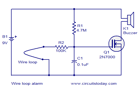
Here is the circuit diagram of a very simple wire loop alarm based on a N-channel enhancement FET 2N700, a buzzer and few passive components.In normal condition the gate of 2N700 (Q1) is connected to the ground through a 100K resistor (R2) and the wire loop. When the wire loop is broken , Q1 will be biased to ON state and the buzzer is activated.The circuit consumes very less standyby current and so the battery will last for a very long period of time.
Circuit diagram.
Notes.
- Assemble the circuit on a good quality PCB.
- The circuit can be a powered from a 9V PP3 battery.
- K1 can be a miniature 9V buzzer.


hello sir!!!
this is quite interesting…….but can u explain its detailed functioning with the explanation on how the wire loop must be made…..
can n type enhancement MOSFET be used?………..
hello sir iam intrested in this project . so can you please expain its working in brief along with the how to use the wire loop section as soon as possible
Hi a readily available IRF450 can be used. but 2N7000 of Fairchild / Vishay is more suited for this project. BUZ74 can also be used. Any N Channel enhancement mode MOSFET can be used for this project.
What is BUZ 74
what if we couldn’t get the 2N7000? what’s the equivalent/s of this FET? thanks …