Class AB Audio Power Amplifier.
Class AB amplifier is an amplifier configuration that stands somewhere between Class A and Class B configurations. A small diode biasing voltage keeps the output transistors ON even if there is no input signal. The transistors will operate normally in their active region for any small input signal.In simple words, one transistor will be ON for more than one half cycle of the input signal. This avoids crossover distortion. Anyway, a small amount of collector current will flow in the idle condition, but it is negligible when compared to the Class A configuration. . A simple, high quality audio power amplifier that can be operated from 12V dc is shown below. Such an amplifier is very suitable for car audio applications. The circuit is very straightforward and uses commonly available components. Power output of this amplifier is around 10W.
Description.
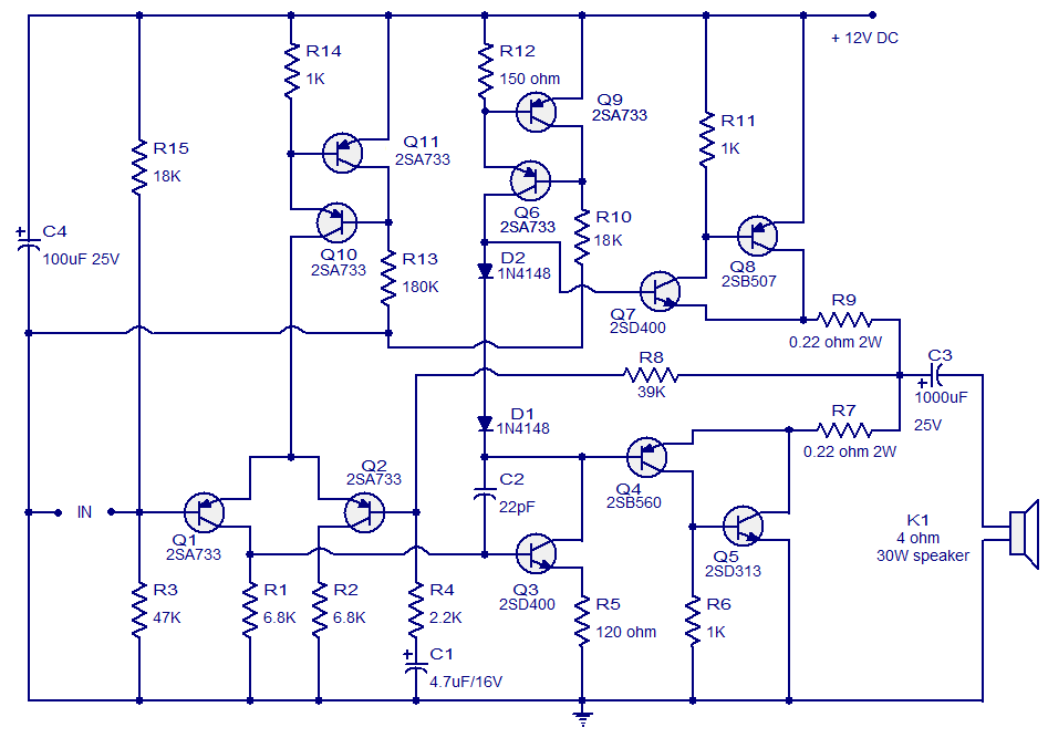
The circuit is purely based on transistors. The first stage of the circuit is the long tailed pair (LTP) built around the transistors Q1 and Q2. Transistors Q10, Q11 and associated components form a constant current source for the long tailed pair. Resistors R15 and R3 are biasing resistors. The second stage of the circuit is built around transistor Q3. Transistors Q9 and Q6 form a constant current source for the second stage. Resistor R8 is the feedback resistor and it plays a vital role in reducing distortion. The final power amplification stage of the circuit is based on the complimentary pairs Q8 and Q5. Q7 and Q4 are the driver transistors for Q8 and Q5 respectively. Audio output is coupled to the loud speaker through capacitor C3. D1 and D2 are biasing diodes. C4 is the power supply filter capacitor. This amplifier circuit can be operated from anything between 12 to 16 volts.
Circuit diagram.

Notes.
- Use 12V DC for powering the amplifier.
- An optional 10K POT can be added in series to the input for volume control.
- Use a 4 ohm/20W speaker as the load.
- Transistors Q8 and Q5 must be fitted to a proper sink.

10 Comments
has anyone tried this circuit? is the circuit working ???
what if we remove the constant current source circuit, from the amplifier, I hope the circuit would also work well
Sir can you tell me the replacement of transistor B560 and B507 ?
I need a Class AB 40 Watt Power Amplifier. Help! 🙂
how do you arrive at 10 watts? i calculate 12V peak to peak, giving 6V peak, max wattage would therefore be 6V^2/(2×4 ohms)=36/8= 4.5 watts?
Any chance you could briefly explain the lack of need for a negative voltage supply for this circuit? its the first I’ve seen that doesn’t require some sort of negative bias. also as a small point the schematic reads 30w Speaker whereas the notes suggest 20w, what would you recommend?
Is there anything we should know about some components need to be place near GND or transistor in proximity to capacitor or what have you … Thanks for this design.
can I use 8 ohms speakers. Then what result can I get.
Hello and thanks for the share of the schematic!
I’m having to design an audio amp with almost the same specs, I have to have output power of 10W but the power driving it should be +/-15V, will this same circuit work by putting -15V at where the ground symbol is, and put the ground between +15 and -15 sources? of course the mic would also go to ground and not to just -15v.
If this will not work for the method I need to do it, can you give me some advice on how to start designing such an amp? 🙂
Thanks
Hi Mohmad use our earlier circuit with +/- 15 volt instead of +/- 12 volt.
https://www.circuitstoday.com/simple-10w-audio-amplifier
Thenk you very much