Digital Potentiomter – Working, Internal Structure & Applications
One of the most common types of variable resistors is the potentiometer. Potentiometer or “potsâ€, are three terminal devices, used to vary the resistance in a circuit. We have dealt in depth about this topic, in our article “potentiometersâ€, if you want to learn about the basics of a pot, this article will be useful for you. Pots that ware available nowadays varies in operation. Some are mechanically operated, while some are digitally controlled.

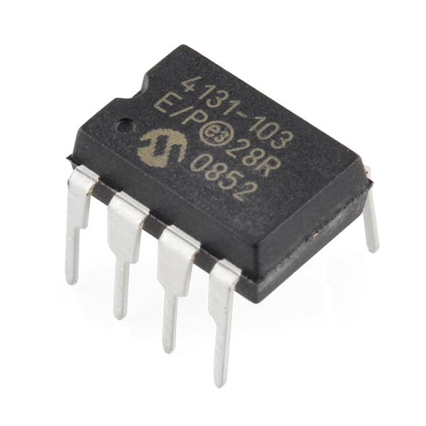
Image Credit – SparkFun
Before we proceed, let’s have a quick review of how the basic working of a potentiometer.
How Digital POT Works?
Generally, a pot has a resistive material over which a wiper moves. This movable wiper controls the resistance offered by the potentiometer. A pot as we know has three terminals, a positive, ground and a wiper terminal. The position of the wiper decides the resistance of the pot. To understand its significance, lets consider the figure below.

Look at the above figure. What do you see, a simple resistor right? Well, there’s more to that. The numbers 1, 2, 3 here indicate the terminal numbers. Terminal 2, indicates the wiper terminal. Now the resistive part between terminals 2 and 3 is nothing but the effective resistance of the pot. So according to this, the effective resistance of the pot, for the first case, where the wiper terminal is nearer to the terminal 1,is higher than that for the second case( wiper terminal nearer to terminal 3).
Now, how to change the position of the wiper? you may wonder. The wiper movement can be controlled either mechanically or digitally. This difference in control of the wiper, brings us to the classification of pots into mechanical and digital potentiometer.
The figure below shows a schematic of a mechanical and a digital potentiometer.

First, let’s see what is common to both of them:
- Basic structure: Both have three terminals and a resistive element, over which the moving terminal glides.
- Adjustable Nature: The resistance of both types of pots can be adjusted to the need of the circuit, and offer wide range of resistances.
Now, if they are similar in structure and nature what’s the difference between the two?
Well, the biggest difference between the two is in their control section.
Control section is nothing but the part of the pot that controls the position of the wiper.
In mechanical potentiometer, the wiper movement is done by hands or we can say physically. In digital potentiometer, the wiper connection is electrical and the movement of the wiper is controlled by digitally controlled signals, typically given out by a computer or a microcontroller.
The types and working of a mechanical potentiometer has been already discussed in our articles “potentiometersâ€. Here in this article, we will deal with the working of digital potentiometers and their advantages over mechanical pots.
What is a Digitally Controlled Potentiometer?
A digital potentiometer or a digiPOT (Electronic Potentiometer) as it is commonly called can be said to be a digital version of the mechanical potentiometer or a rheostat. It offers the same analogue functions as a rheostat or a potentiometer that is control of current or voltage. It is controlled by digital protocols like I2C , SPI, and basic up down and push button protocols.
This device allows a more accurate robust and faster calibration process, with smaller voltage glitches.
How is digiPot different from the traditional Pot?
- The Build:
Mostly, the digipot is built from a resistor ladder integrated circuit. Here, at each step, there is a switch that connects it to the output of the potentiometer. When a particular step is selected, the effective resistance is calculated from that point to the ground. So, obviously, higher the number of steps, higher number of values will be available in the digiPot (that is a higher range of resistance values offered by digiPot).Now you may have question that how do we determine the number of steps, like what is the indication of number of steps in a digiPot? The answere is simple, a bit value, indates the number of steps of the resistor ladder, that is if a digiPot has N number of bits , it means 2NÂ steps are avaible. For example, a bit number 8 indicates there are 28 = 256 steps. This bit number is also called the resolution of the digiPot. The most commonly used resolution are 8, 5 and 10 Bits.
Other method on which a digiPot is built is the digital to analog converter, but is not as common as the resistor ladder circuit.

2. The Memory
However, there are some digiPots which use Non volatile memory too. Here, the last step is retained even if they are powered down.
3. The Control Section
We know that the control section of the DigiPot is what makes it different from the tradition potentiometer(or the mechanical pot). Let’s have a look what happens in a control system of a digiPot.
Figure shows the control of a typical electronic potentiometer.

A synchronous or an asynchronous serial bus is used in the control circuit of most of the potentiometers. Other than the serial bus, some pots also use control logic or front panel switches.
The increment/decrement interface bus is the most common asynchronous bus. Figure below shows a basic control section with asynchronous bus.

Here, signals used are:
CS: The chip select signal, when enabled is used as an address input for multiple digital pot applications.
U/D:  The up/down signal is enables to set the direction of the pot’s wiper.
INC: This signal controls the wiper movement. On every falling edge of the increment signal INC, the wiper moves.
The SPI, I2C, two wire, and microwire-like buses are the common synchronous buses. Out of these I2C is the most common and its interface diagram is shown below.

Here the main signals are:
SCL/SCK: SCL or SCK, is the serial clock of the interface. This when enabled, synchronizes the control section.
SDA: These are the separate serial data lines, to transfer data from the interface to the control section. They are bidirectional in nature.
These are the main features of DPP that distinguishes it from the traditional potentiometer.
Now lets see how the mechanical and digital potentiometers are different from each other.
Mechanical V/S Digital Potentiometer Circuit
The wiper resistance:
- Mechanical pot: Negligible resistance
- Digital pot: The resistance is around 100Ω.
End-to-end resistance
- Mechanical pot: Independent and well controlled, as it is done physically.
- Digital pot: Dependent on the input control signals with a tolerance of 20%. Although, the ratio between the wiper postions are constant.
Interface:
- Mechanical pot: A well controlled mechanical interface, meaning the wiper position is controlled physically by hands.
- Digital pot: Mostly controlled by a microprocessors, push buttons or the most common serial bus interfaces such as I2C , SPI or Asynchronus
So, now that we have covered on the subject “Digitally Controlled Potentiometer”. You must be wondering where does this device find its applications. Lets have a look into that.
Applications
For any application where a parameter has to be regulated, adjusted or controlled, use of digital potentiometer circuit is a good choice. Below are some of the applications of it:
- To control voltage, current , resistance power duty cycle , Q factor etc in an electric circuit.
- To vary the resistance in an analogue circuit.
- To adjust the volume in speakers and other appliances.
- In joysticks, motor control and automated calliberation
- To adjust brightness and contrast in LCDs
- Programmable Voltage Regulator
- Sensor Auto Referencing Circuit
- Programmable I to V Converter
- Automatic Gain Control

Good article, really explains everything in detail. Carry on