An inverter is used to produce an un-interrupted 220V AC or 110V AC (depending on the line voltage of the particular country) supply to the device connected as the load at the output socket. The inverter gives constant AC voltage at its output socket when the AC mains power supply is not available.
Let’s look at how the inverter makes this possible. To grasp the functioning of an inverter, we
should consider in the following situations.
- When the AC mains power supply is available.
- when the AC mains power supply is not available.
When the AC mains power supply is available.
When the AC mains supply is available,the AC mains sensor senses it and the supply goes to the Relay and battery charging section of the inverter.AC main sensor activates a relay and this relay will directly pass the AC mains supply to the output socket.The load will by driven by the line voltage in this situation.Also the line voltage is given to the battery charging section where the line voltage is converted to a DC voltage(12V DC or 24V DC usually),then regulated and battery is charged using it.There are special circuits for sensing the battery voltage and when the battery is fully charged the charging is stopped.In some inverters there will be a trickle charging circuit which keeps the battery constantly at full charge.
When the AC mains power supply is not available.
When the AC mains power supply is not available,an oscillator circuit inside the inverter produces a 50Hz MOS drive signal.This MOS drive signal will be amplified by the driver section and sent to the output section.MOSFETs or Transistors are used for the switching operation.These MOSFETs or Transistors are connected to the primary winding of the inverter transformer.When these switching devices receive the MOS drive signal from the driver circuit,they start switching between ON & OFF states at a rate of 50 Hz.This switching action of the MOSFETs or Transistors cause a 50Hz current to the primary of the inverter transformer.This results in a 220V AC or 110V AC (depending on the winding ratio of the inverter transformer) at the secondary or the inverter transformer.This secondary voltage is made available at the output socket of the inverter by a changeover relay.
Automation in an Inverter.
Inverter contains various circuits to automatically sense and tackle various situations that may occur when the inverter is running or in standby.This automaton section looks after conditions such as overload,over heat,low battery,over charge etc.Respective of the situation, the automation section may switch the battery to charging mode or switch OFF.The various conditions will be indicated to the operator by means of glowing LEDs or sounding alarms.In advanced inverters LCD screens are used to visually indicate the conditions.
——————————————————————————————-
Block diagram of a basic inverter.
——————————————————————————————-
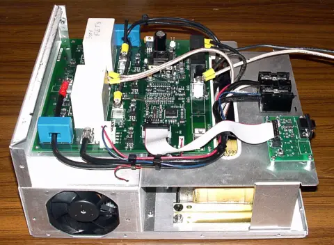
Inside of an Inverter.
——————————————————————————————-
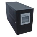
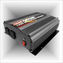
Some commercially available inverters.


49 Comments
Hey sir really this is amazing information , sir can use IGBT in Inverter for Switching purpose please reply sir.
need design of DHS-inverter if anyone have please upload that
transformer connection
send me 600va inverter circuit diagram inverter transformer connection
My square wave inverter when connected to mains power supply gives a click sound and then comes on battery mode: means supplies power through battery and stops charging. What may be reason?
thanks for invorter details…
i want to build a 1.5kva inverter as my project.i will be glad if you could help with materials (if you have any) and circuit
how to show a model for invertore
What is the specification of the relay used in the home inverter ? If i want to buy at a shop what should I tell him ?
Pls can u explain to me on how i can construct a 1200w transformer or how to obtain 1.thanks
I am excited about your Store and am eager to shop and order! However I live in the USA and know only our currency in U.S. dollars and cents, do you ship here? How much will it cost? And, do you have a schematic design to make/build a variable Wifi hotspot box?
@Ed
Currently we don’t ship to US. We have some legal formalities to clear before shipping to foreign countries. We will definitely let you know once we are ready.
regards,
Jojo
when power Is gone.then inveter is gave ac&dc
pleas send principle inverer
thanks
thx for advice..
Very good explained Thankssss
plase,send to mail addrss “ac inverter block digram & explin”
http://sandysplash.blogspot.in/
Its Simple and Precise Thanks………
how to make inverter?
plase,send to mail addrss “ac inverter block digram & explin”
im very much new to this electronic stuff and not able to understand MOS and MOSFET stuff. I would be very happy if u can teach this in some very basic stuff. Im gud at concepts in electricity..
Sg3524 is the best ic 4 inverter..plz how can hi connect lcd to indicate automation
I want you to help me to explain the different section of the block diagram of the inverter shown above. Thanks
Hi Alexander if you donot want to step up or down you can use you H bridge final stage (with the required output as input DC).
how to design a transformerless inverter
how to make an inverter at home; and sound system as woofers….plzs
Plz help me to make an inverter
I am interested to make one inverter.pls guide&provide information to me
pls help me how to prepare inverter
PLEASE SEND TO MAIL ADRESS DC TO AC INVERTER CIRCUIT DIAGRAM AND ITS EXPLANATION ON HOW THE CIRCUIT WORKS
Pls kindly help me with links on how to constuct transformers for inverters
it’s very good description about an inverter. It’s sufficient for a reader to make taste in reading and studying about inverter.good very-99 good.
I want to make one inverter, could you please provide me the circuit diagram for 500 or 650 Watt.
please i want to come up with an 1800watts inverter,advice about the latter
i want know in detail the inverter operation
i want to know in deatil about inverter working
hi i am mahesh kumar from ludhiana, punjab i want how make lead acid battery low maintenance, not chek water , how
E X C E L L E N T
Hi Mona you may go through 100 watts inverter and 12 volt battery charger circuits appeared in Circuits today, that will give you the idea of the blocks shown.
i wan inner design of each block in that inverter can u help me thanks
send me 500w inverter circuit diagram…..
thanks..
I m interested to improve the working efficiency of the inverter …. so will be thankful if u can provide the circuit diagram of inverter to my email….
Reply to HK
Take a look at these links
https://www.circuitstoday.com/60w-inverter-using-transistors
https://www.circuitstoday.com/introduction-to-pwm-inverters
https://www.circuitstoday.com/simple-40w-inverter
https://www.circuitstoday.com/100-watt-inverter-circuit
hi
i am interested in power saver circuit.please help me like what should i do to make to this circuit.anyone help me for makinhg power saver circuit with stabilizer?
Thanks for inverter details………..
i’m interested in this inverter circuit. now could you please advice me like what change should i make to the circuit for 1000W. thanks
i will add a 1000W inverter circuit soon.pls keep visiting