Potentiometer – Working, Circuit Diagram, Construction & Types
Resistor, a small bundle of resistance, is one of the most used basic components in an electric circuit. Mostly used to regulate the current flow by adding/subtracting resistance from the circuit, these resistors are available in many shapes and sizes. These resistors can be broadly classified as fixed and variable resistors. As their respective names suggest, a fixed resistor has a single fixed value of resistance, whereas a variable resistor has resistance value over a defined range. Out of the numerous linear and Non-linear variable resistors available, the most common is the Potentiometer. This article deals with the working principle, construction and application of a potentiometer. So let’s get started!
Potentiometer (pot)
The potentiometers or the “potsâ€, as it is commonly known in the electric circles, is a three terminal variable resistor. Out of its three terminals, two of them are fixed and one  is a varying (linear / rotary) terminal.
The value of the resistance can be changed from zero to a defined upper limit, by just manually sliding the contact over a resistive strip. As the resistance changes, the current through the circuit changes and hence according to the ohms law, the voltage across the resistive material also changes.
Since it coverts rotary or linear motion by the operator into a change in resistance(hence a change in electric parameter), it can be called an electro-mechanical transducer. They are passive in nature, therefore dissipate power rather than supplying power to the circuit.
In its early days of manufacture, it was thought of like a large wire wound resistive coil,which could be adjusted so as to measure the voltage difference across it . Hence, the name “potentiometer†was given to this device, which is coined from the combination of two words: potential difference and metering.
They have come a long way since then. Gone are the days of large bulky potentiometers, now what we get is quite small and easy to use and light to carry; also they have now used in wide range of applications.
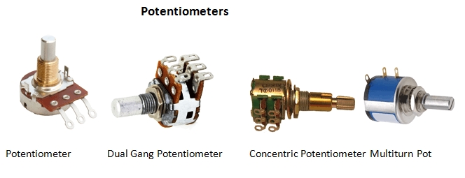
Now that we have had an introduction about the potentiometer, you might have a curiosity of knowing how it looks like. Figure 1 shows some practical pots, while figure 2 shows the standard symbol of the same.


It is represented by a zigzag line with an arrow pointing inwards at the center.
Next lets discuss the very crux of this article, the working principle of the potentiometer.
How does it work?
As already discussed, a potentiometer has three terminals. When connected to a circuit, the two fixed terminals are connected to the ends of the resistive elements while the third terminal is connected to the wiper.
In the circuit diagram shown  below,  the terminals of the potentiometer are marked 1, 2 and 3. The voltage supply is connected across terminals 1 and 3, positive lead to terminal one while negative lead to terminal three.  The terminal 2 is connected to the wiper.

Now a closer look into the figure, we can see that at the current position of wiper, there are two resistive paths just like the resistor is split into two resistors. Out of these two resistors, the one having longer resistive path will have a higher resistance. This is due to the fact that resistance of a resistor depends on its length (since R=Ï). Higher the length, higher is the resistance, provided the material of the resistor and its cross-sectional area remains same.
For simplicity, lets name the two resistors, R1 and R2 (Refer figure). The wiper voltage is actually the voltage across R2. The circuit now looks like a voltage divider, where the output voltage is given the equation:
Vout = Â {R2/(R1+R2)} x V; where V= supply voltage.
So clearly, if we want to change the output voltage, we can just change the value of R2, by sliding the wiper towards the terminal 3. When the wiper is at terminal 1, R1 becomes zero and the voltage across the wiper is same as the supply voltage.
Also, when the wiper is at terminal 3, the effective resistive path for R2 is zero, hence the resistance R2 Â is zero.
The working principle can be made clearer, by solving the example below
EXAMPLE 1:
A resistor, R1 of 150Ω is connected in series with a 50 Ω resistor, R2 acrosss a 10 Volt supply ohm resistor as shown . Calculate the total series resistance, the current flowing through the series circuit and the voltage drop across the 50 ohm resistor.

Solution:
Since the two resistance are in series, total resistance R = R1 +R2 = 200Ω. The current flowing through the circuit will be I = V/R =10/200 = 0.05A. Voltage drop across R2 = 50Ω can be found by voltage division rule, that is
VR2= 10 × (50/200)= 2.5 V
Here we see if we change the value of either R1 or R2the value of the voltage across any one of the resistors will be in the range of 0-10V, provided that the total resistance of the circuit remains constant.
This very concept is the principle behind the working of a potentiometer. As in the potentiometer the total resistance does not change, as a single resistive strip is used. The split of resistor is done by the wiper. And therefore the resistance values vary as the position of the wiper varies.
Now that we have discussed the working principle, lets now learn how this passive device is constructed.
Construction of a Potentiometer
The potentiometer essentially has a resistive element over which a moving terminal, the wiper slides. Any potentiometer is constructed of the following parts:
- The terminals: As already discussed, the potentiometer has three terminals, two fixed and one variable.
- The resistive element: This part is the main part of the device and it is connected to the two fixed terminals. It is one of the decisive aspects when it comes to the cost of the potentiometer, and also can govern aspects of the performance of the component including the power dissipation capability and noise generated. The resistive element used can be of the following types:
- Carbon Composition: This is made from carbon granules and is one of the most common types of resistive material used, because of its low cost. It also has a reasonably low noise and lesser wear than other naterials. However, it is not that accurate in its operation.
- Wire wound – These are basically Nichrome wires and are wound over an insulating substrate. They are mostly used in high power applications and last really long. They are precise but have limited resolution.
- Conductive plastic: Often used in high end audio applications, they have very good resolution but are really costly, and can be used in low power applications only.
- Cermet: A very stable type of material, it has a low temperature coefficient and is highly resistant to temperature. However, it has a short life and can burn a hole in your pocket.
- The wiper: This is the one terminal that slides over a resistive strip to make an electrical contact. It may be a rotary wiper that is like a half an arc, that covers over ¾ of a circle or a linear wiper.
Angular position of the rotary wiper in degrees is given by the formula:
θ = (Vout/Vsupply)
- The shaft: In case of a rotary wiper type potentiometer, a shaft is present over which the wiper is fabricated.
- Casting: All of the components is housed inside a casting, to prevnt it from external physical damages

There are some particular characteristics of a potentiometer that one needs to know. Next section deals with that.
Characteristics of Potentiometers
Some of the characteristics of a potentiometer are:
- TAPER: The law of pots or the taper of pots is one such characteristic of potentiometer in which one needs a prior knowledge, to pick the right device for the desired application. It is nothing but a ratio between the wiper position and the resistance. This ratio when plotted may be linear, logarithmic or antilogarithmic, as shown in figure.

- MARKING CODES: While selecting a potentiometer, you need to know the maximum value of resistance it can attain. For this purpose, the manufactures use marking codes, which indicate the same. For example, a pot with a resistance of 100K marked on it means, the maximum limit of the pot is 100kΩ.
Since, we also need to know the taper of the pot, the manufacturers use marking codes for indicating the taper of the pot as well. The marking codes differ from a region to region. One must have prior knowledge of what a code stands for.
- RESOLUTION: As we vary the resistance in the pot, there is a minimum amount of resistance that can be changed. This is known as the resolution of the pot. For example, if I say the resistance of pot is 20kΩ, with a resolution of 0.5, the minimum change in resistance will be 0.5Ω, and the values that we get for the smallest change will be 0.5,1.5,2Ω and so on.
- HOP ON HOP OFF RESISTANCE: Like we have seen in the construction part of this article that the resistive element is connected in between the two terminals. These terminals are made of very low resistance metal. Hence, whenever the wiper enters or exits this region, there will be a sudden change in the resistance. This characteristic of the pot is called, hop on hop off resistance.
Now that the characteristics of the pot have been discussed lets have a look into what are the types of potentiometers.
 Types of Potentiometers:
Even though the basic construction and working principle of potentiometers are the same, they differ in one aspect that is the geometry of the moving terminal. Mostly the potentiometers what we find has a wiper that rotates over an arc shaped resistive material, there is another type of pot where the wiper slides linearly over a straight resistive strip. Based on the geometry of the resistive strip, the potentiometer can be broadly classified into two types, discussed below.
- Rotary type potentiometers: As the name suggests, this type of potentiometer has a wiper which can be rotated across the two terminals, to vary the resistance of the potentiomer. They are one of the common types of Pots. Depending upon how many times, one can turn the wiper, they are further classified into the following categories:
- Single turn : These pots are one of the commonly used type of pots. The wiper can take only a single turn. It usually rotates a 3/4th of the full turn.
- Multi turn: These pots can make multiple rotations like 5, 10 or 20. They have a wiper in the form of a spiral or helix, or a worm-gear, to make the turns. Known for their high precision, these type of Pots are used where high precision and resolution are required.
- Dual gang: From the name of this pot it can be assumed what it is. It is nothing but two pots with equal resistance and taper are combined on the same shaft. The two channels are set in parallel.
- Concentric pot: Here two pots are combined together on shafts placed ina concentric manner. The advantage of using this type of pot is that two controls can be used in one unit.
- Servo pot: “Servo†meaning motor pot is a motorized pot. This means its resistance can be adjusted or controlled automatically by a motor.

- Linear type potentiometers: The next type of pots is one in which the wiper slides over a straight resistive strip. They are also known by the names such as: slider, slide pot or fader. They are further classified into the following types:
- Slide pot: This is the basic type of a linear pot. They have a single resistive strip over which the wiper slides linearly. They have a good precision and are moistly made from conducive plastic.
- Dual slide pot: This type of linear pot is just the calliberation of two slide pot in parallel. This means it has a single slider that controls two pots in parallel.
- Multi turn pot: In an application where precion and good resolution of utmost importance this type of pto is used. IT HAS a spindle, that actuates the slider, that can turn upto 5, 10 or 20 times to imporove the precision.
- Motorized fader: As the name suggests, the movement of wiper of this pot is controlled by a motor, and hence its resistance.

Applications of Potentiometers
A potentiometer essentially works as a voltage divider, however it is used in many industries and applications too. Some of the applications are listed below, categorically:
- Pots as Controllers:
- Potentiometers can be used in user controlled input applications, where there is a requirement of manual variation in the input. Like for example a throttle pedal is often a dual gang pot, used to increase the redundancy of the system. Also, the joysticks that we use in machine control, is a classic example of pot used as a user controlled input.
- Another application where pots are used as controllers are in audio systems. The potentiometer with logarithmic taper, is often used in audio volume control devices, this is so because our hearing has a logarithmic response to sound pressure. A logarithmic taper pot will therefore natuarally make the transition from a loud to soft sound( and vice versa), smoother to our ears. Mostly a motorized pot(with logarithmic taper) is used for this application.
- Pots as measuring devices:
- Most common application of potentiometer is as voltage measuring devices. The name itself has that implication. It was first manufactured for the porupuse of measuring and controlling the voltage.
- Since these devices convert the positon of the wiper into an electrical output, they are used as transducers to measure distance or angles.
 3. Pots as tuners and calibrators:
Pots can be used in a circuit, to tune them to get the desired output. Also during the calibrations of a device, a preset pot are often mounted on the circuit board. They are kept fixed for most of the time.
With this we have covered almost all the aspects so that now you know the basics of a potentiometer. Lets have a quick recap of what we learnt:
- Potentiometer or pots are three terminal variable resistors.
- Two terminals are fixed, one is a sliding contact.
- The sliding contact is often referred to as wiper
- Wiper moves over a resistive strip.
- The position of wiper on the resistive strip decides the resistance of the resistor.
- Resistive strip can be composed of carbon, or may be wire wound. Even a conducive plastic may be used as a resistive strip
- Geometry of the resistive strip whether it is an arc or a straight strip, decides the geometry of the potentiometer.
- Types of potentiometer: Linear and Rotary.
- The taper, resolution, hop on hop off resistance and the marking codes are the main characteristics of a potentiometer.
- There are many applications of a potentiometer, from audio controller circuit to measuring distances, angle or voltages. It is very versatile in nature.
Hello you far away, excellent articles even for an old electronician as me.
I do like have the same infos about capacitors as Mylar, plyester and others,why their applications is recommanded in a circuit
instead of another model?
Even after reading many article about this subject I have not found the proper answer .
Thank you for your answer.
Jacques Carre Land (from France)