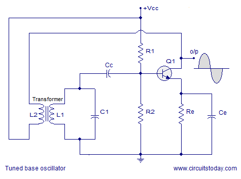
Tuned base oscillator.
Tune base oscillator is another type of transistor based LC oscillator where the tuned circuit (tank circuit) is placed between the base and ground of the transistor. The tuned base oscillator is also called “Armstrong oscillator” after the name of its inventor. The tuned circuit essentially consists of a transformer and capacitor connected in parallel. The circuit diagram of a typical tuned base oscillator is shown in the figure below.
Circuit diagram.
In the circuit diagram, resistors R1 and R2 forms a voltage divider bias for the transistor Q1. Emitter resistor Re is meant for stabilizing the bias point. Ce is the emiiter by-pass capacitor. Its job is to by-pass the amplified AC signals from dropping across Re. If the amplified AC signals are dropped across Re, it will add to the base-emitter voltage (Vbe) of the transistor and affect the DC biasing conditions. Cc is a DC blocking capacitor. Its job is to prevent DC currents from the tank circuit side from entering the base. Primary coil (L1) of the transformer and the capacitor C1 forms the tank circuit.Working of the tuned base oscillator.
When power supply is applied, the transistor Q1 starts conducting and its collector current starts to rise. From the circuit diagram, you can see that this collector current actually flows through secondary coil L2. This rise in current current through the secondary induces some voltage across the primary coil L1 by virtue of mutual induction. The secondary coil L2 is also called “Tickler Coil”. The induced voltage across L1 charges the capacitor C1 to the maximum. Now the energy stored in the coil L1 as electromagnetic field is transferred into the capacitor as electrostatic field. Now the capacitor starts discharging through L1 and the current through L1 starts increasing. When the capacitor is fully discharged, there will be no more emf left across the capacitor to maintain the current through L1 and so the magnetic flux around the coil tends to collapse. The coil L1 produces a back emf by virtue of self induction. This back emf charges the capacitor C1 again. Then the capacitor discharges through L1 and the cycle is repeated. The repetitive charging and discharging cycles result in a series of oscillations in the tank circuit.
These oscillations are coupled to the base the transistor through capacitor Cc and it appears in amplified form across the collector of the same transistor. A portion of the collector voltage is inductively coupled to the tank circuit by the secondary coil L2 for compensating the losses in the tank circuit. The winding directions of L1 and L2 are so selected that there will be a phase difference of 180° in between. Thus the feedback system produces a phase shift of 180° and the transistor arranged in common emitter configuration provides another 180° phase shift. So the total phase shift between the input and output becomes 360° and the conditions for positive feedback and sustained oscillations are met.
If the feedback is too low, the oscillations will die out in time and if the feedback is too high the output will be distorted. The feedback fraction can be adjusted by varying the turns ratio of the transformer. The frequency of oscillations of the tuned collector oscillator can be expressed using the following equation:
F = 1/[2π√(L1C1)]
Where F is the frequency of oscillations. L1 is the inductance of the primary of the transformer and C1 is the capacitance of the capacitor in the tank circuit.
Testing the tuned base oscillator circuit.
Added soon.


Comments are closed.