Tone control circuit.
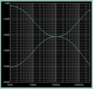
This is just another circuit designed by Mr. Seetharaman Subramanian and time it is a high quality passive tone control circuit that has an overall gain of around 25 with 20dB boost and cut. This circuit needs minimum number of components, is very cost effective and most of the components required can be found from you junk box. Even though an opamp which is an active element is used in the circuit, the tone control section is entirely passive and that’s why the circuit is named so.
Description.
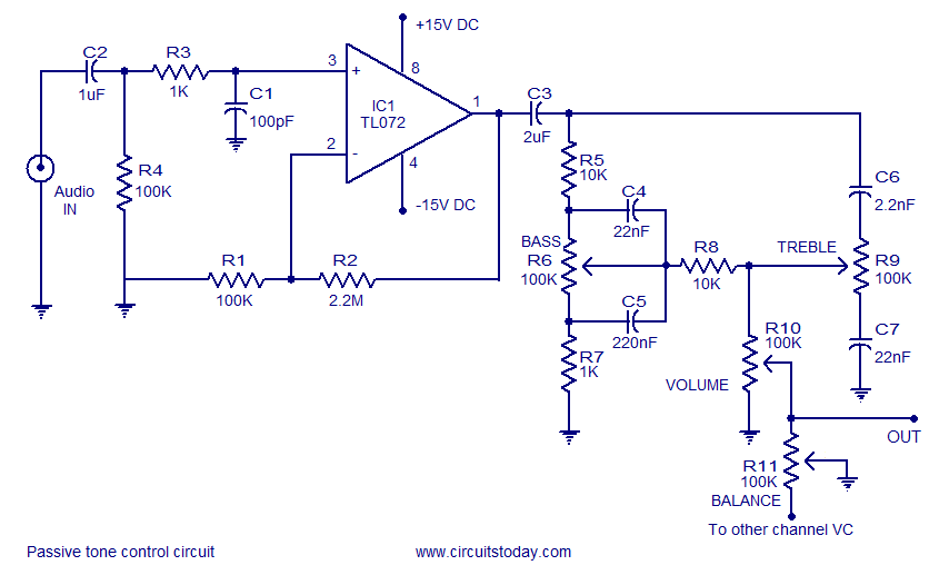
The circuit consists of two parts. Firstly an op-amp based preamplifier stage and secondly a passive Baxandall tone control circuitry. The preamplifier stage is a non inverting amplifier based on TL072. R2 is the feedback resistor which together with resistor R1 sets the gain of this stage and with the stated values it is 23. Voltage gain in the non-inverting mode is expressed using the equation Av= 1+ (R2/R1). Value of R3 (Rin) is taken as approximately equal to the output impedance of TL072. C2 is the input DC decoupling capacitor and it also sets the low frequency cut off limit. R4 is the offset minimizing resistor which reduces the effect of output offset voltage on the output of the amplifier and its value is taken as approximately equal to R1||R2. The preamplifier stage is powered using +15/-15 dual supply. Capacitor C3 couples the preamplifier stage with the tone control stage.
The tone control stage is a passive Baxandall tone control circuit that can produce a 20dB cut or boost. POT R6 is used for controlling the bass while POT R9 can be used for controlling the treble. POT R10 serves as the volume controller while POT R11 can be used to adjust the balance. Resistor R8 provides some isolation between the bass control and treble control stages.
Passive Baxandall tone control circuit: Also known as James Network is a circuit for independently adjusting the bass and treble for high quality audio applications. The circuit is entirely based on passive components and the performance is very superior. In many older passive tone control circuits there was much interaction between the two controls and there was a great deal of asymmetry. Such problems are completely eliminated in Baxandall tone control circuit.
Circuit diagram.

Seetharaman’s words about the circuit: Iam just enclosing you the TL072 (TL062 or 82 also can be used) passive tone control with 20dB boost and cut with a overall gain of around 25. you can also give an overall feedback if required, from output to TL072 inverting input through suitable resistance.
Dual supply for this circuit.
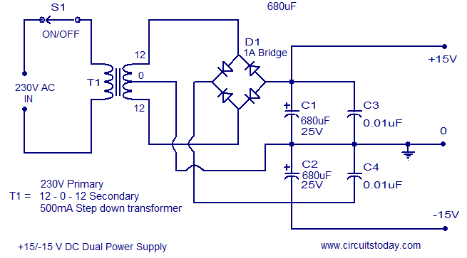
A +15V/-15V dual supply for powering this tone control circuit is shown below. Bridge D1 can be made using four 1N4007 diodes. This supply is unregulated and its quite fine for this circuit. Anyway if you need to have a regulated one please inform me.

Notes.
- Circuit can be assembled on a vero board or perf boad. Any way a PCB is the best option.
- Use +15/-15V DC dual supply for powering the circuit.
- IC1 TL072 must be mounted on a holder.
- By changing the value of R1 and R2 the voltage gain (Av) of the preamplifier stage can be changed.


Few other tone control circuits that you may find useful.
1.Two transistor tone controller
2.Baxandall tone control circuit
3.HiFi DX bass circuit
4. Stereo pramplifier with tone control


54 Comments
The FET op-amp has very high effective input impedance, yet this circuit has a 100K to ground in the immediate input (after the capacitor AC coupling). I need a similar circuit that will not load the output from an acoustic guitar passive transducer. Can I put a FET follower in front of this circuit to make have high input impedance?
Thanks for posting this awesome design!! Just built two of these without the pan pots using opamp lf353p. I summed both to a mono output to create a small crude two channel audio mixer. I chose not to build the power supply, instead I’m powering using 4 9V’s run in series to create a dual voltage supply of +/-18V. I think this will work for me until components start burning out. lol
Thanks again for this and keep up the great work…
Car speakers may be quirt effortlessly fixed in to the
car either by yourself or by an expert that your dealer may
well recommend. When I enter the housing unit I have been assigned to
I see that I will be sharing a cubicle with seven other individuals.
The Black – Berry mobile platform is also an awesome media device
able to hold a vast library of your favorite mp3 music to
keep you entertained for hours on end.
please explain the purpose of the pin “to other channel VC” ????
Sir can i use KA4558 instead TL072?
KA4558 is a Bipolar device but TL072 is MOS FET device with better spec and slew rate. YOU can try 4558 if performance is poor replace it with TL072
Sir can i supply 56-0-56V in 150W amplifier? Thank you.
sir i have a problem hope you can help me, i have build this circuit and to my surprise when i connect it up it play very low even when i turn the volume up, what could be the problem.
It should work may be your input is quite low. Try by increasing the input, still no improvement. Check the wiring and all component values. Try by changing the IC with new one. Try 47 K for R1. This is a proven circuit.
thanks for replying, i will do what that and let you know what the out come is thanks again.
thank u sir I will do just dat.
thank u sir. after making my 150 Watt amp (which I intended using as subwoofer)I powered it with 30-0-30(+42 0 -42)n d output transistors(tip 147 & tip 142) collectors & emitters got shorted without input & output connected. but with d2390 & b1560 it works fine but with less output power
can dis circuit be used to run a single power supply amplifier e.g d motion feedback amp?
Hi Abubakar you have to use single supply amplifier and preamp together. You cannot mix single supply and dual supply circuits. Use the two transistor tone control appeared earlier for Motional Feed Back amplifier.
can dis circuit run on 12volts ????
No you can use TDA1524 tone control chip which is meant for 12 volts https://www.circuitstoday.com/stereo-preamplifier-with-tone-control
or you can use the following simple 2 transistor circuit both appeared earlier in our project.
https://www.circuitstoday.com/two-transistor-tone-controller
Sorry for my correction for this. The circuit of power supply is wrong. Diode Bridge rectifier is backwards.
The junction point of two cathode is positive, and to be connected to +C1 and +C3 and the junction point of two anode is negative (to be connected to -C2 and -C4.
Thanks,
Yasir isnan – Indonesia
Thanks. Yes you are correct all diodes in the bridge rectifier, anode and cathode to be inter changed.
Mr Rex you can use higher current transformer not higher voltage. current capability of transformer has nothing to do with the performance. higher voltage will kill the circuit.
Seetharaman, instead of 500MA Current, can i use 1.5 ampere of transformer for the passive tone control or wil 1.5 ampere damage the tone control
Setharaman, i have three question… (1) 680uf capacitor for the power supply is hard to find in my place.. Can i use 1000uf (2) what is the current rating of the transformer how many ampere (3) the 0.01uf capacitor in the power supply is it polyester or ceramic disc
Hi Friend
I have to use this circuit in the car audio system, i have in home the OP AMP TL074, my question is, i can supply the OP amp with +12V in the Pin 4 and ground in the Pin 11 ??
Thanks
There are errors in the power supply circuit. The bridge rectifier is backwards.
Also the junction point is not indicated at the d1,c2,c4 node.
Please sir i need on my last comment
ineed a circuit analysis
Good day sir, Im really confused about the Vc channel. Can i connect the balance which you wrote to other vc channel. Can i connect it with the passive tone control output. Thank you sir for reading. Im waiting for your reply before i go crazy.
Hi Prince Yes it is to other channel volume control. Only one channel is shown the other channel is identical. You can use stereo ganged control, so you can operate the control of both channels together. TL072 is a dual opamp, hence you require only one IC for both the channels.
Hi, I have a few questions about the circuit itself. (I’m sorry if they are stupid questions it’s just that I have never done any audio preamp).
In the balance control when you refer the other potentiometer pin “To other channel VC” you refer to the other channel Volume Control or something else?
Is it a stereo preamp or do I have to make another preamp for the other channel? In the last case how can I adapt this circuit in such a way that with the same potentiometers I adjust things for both channels?
Thank you very much, and sorry for the questions and my english.
Yes it is to other channel volume control. Only one channel is shown the other channel is identical. You can use stereo ganged control, so you can operate the control of both channels together. TL072 is a dual opamp, hence you require only one IC for both the channels.
Seetharaman, how can i wire this circuit to work with single power supply
Hi Rex instead of modifying this circuit you can use TDA1524A
https://www.circuitstoday.com/stereo-preamplifier-with-tone-control or discrete transistor circuit
https://www.circuitstoday.com/baxendall-tone-control-circuit
Most suited ones for single supply power amplifiers.
Hi Rex use TDA1524A a good tone control for single supply operation.
Hi Rex use a simple transistorised baxendall-tone-control-circuit appeared earlier which will also be ideal.
Seetharaman, the power supply for this Tone control has no regulator, Please give us the circuit for regulated power supply,
Hi Rex no need for regulation for this tone control. A well smoothed supply with least ripple is the requirement. the supply shown above is just sufficient. If you still feel regulated is better use 15-0-15 volt transformer with 15 volt positive (7815) and 15 volt negative regulator (7915)for the power supply. use our earlier circuit for reference
https://www.circuitstoday.com/regulated-dual-power-supply-circuit
Seetharaman, the power supply for this Tone control has no regulator, Please give the circuit for regulated power supply,
Please give the circuit for regulated power supply
hi rohin ihad been finished assembled this passive tone control,using C2 1uf/25v and C3 2.2uf/25v and its working driving my 150 watt amplifier,but there was a little bit humming,,,is there any other components used to modify this to eliminate humming?
longing your reply soon. thanx
what is C2 and C3 electrolytic capacitor or ceramic?
polyster cap. or np electrolite cap..if you could not get them you can make a np cap. with two p cap. for make a 1 uf (105) take two 2uf cap. (which are electrolite polarity) weld their positive legs and rest of both legs which are negative , use them .now it become 1uf non polarity capacitor.and for 2uf (205) use two 4uf cap. rest procedure is same.
what capacitor can replace 2uf and 2.2 nf, is not avbailable in our market,,,i need this tone control.
hello sir my amplifier(dual power)18 volts 5A
this circuit IC TLo72 what is max.volts
Hi, what kind of capacitors are required for this pre-amp, and what is the ideal voltage rating?
Thank you
Sir Iam not able to find TL072IC please provide me any alternative
sir can I use 6A4 diodes in the power supply circuit instead of IN4007????
Hi Cooldon you can try M62446AFP chip most effective one it is available in stores as kit form.
http://pdf1.alldatasheet.com/datasheet-pdf/view/247572/RENESAS/M62446AFP.html
hello SEETHARAMAN pls i dont know if any have a DIGITAL VOLUME AND TONE CONTROL.Pls i need it tanks,i will be waiting
hello every body i just finish this circuit and it is working very fine,pls i dont know if any body has a DIGITAL VOLUME AND TONE CONTROL.Pls i need it tanks,i will be waiting
hello every body i just finish this circuit and it is working very fine
Hi Tanker go through the following circuits Fig.2 shows the technique used.
http://www.eng.yale.edu/ee-labs/morse/compo/sloa058.pdf
how can I modify this circuit to single supply?
Hi Rolfi you are correct. Thanks for your observation, it is an ideal requirement. logarithmic control have to be used for linear indication of knob position.
Getting these potentiometer are a bit difficult and their tracking error between pots also give a difference in frequency response of both the channels in the ganged potentiometer. It is the reason just linear pots are sufficient as they track between both the tracks of ganged potentiometer. If you use independent potentiometers (for bass, treble and volume)for each channel then log pots can be used comfortably, which is also correct.
Yes, this one of the real veterans among tone control circuits. But I do believe that all of the potmeters need to exhibit a logaritmic curve. With linear potmeters, you will still have boost and cut, but proper adjustment will be very difficult. And the REAL veteran circuit even used a (double) log-antilog potmeter for channel balance!
I assembled all the components but my circuit is not run,what can be a problem?
Have you used both + and – supply. check the wiring thoroughly. This is a proven circuit it should work. all indicated as ground should be connected to zero volt reference (common to + and Minus supply. Please check.